Page 382 - Din prodcuts 2020
P. 382

4/28             ELECTRICAL INSTALL ATION SOLUTIONS FOR BUILDINGS   2CHC 420 001 C0201


          —
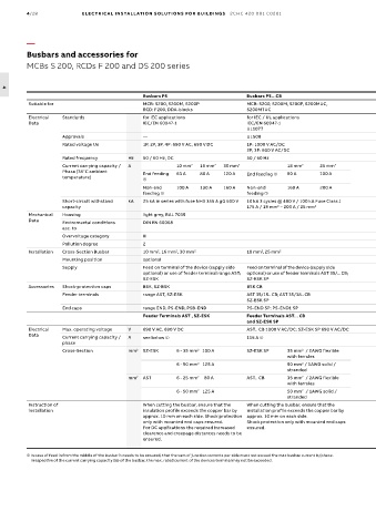
          Busbars and accessories for
          MCBs S 200, RCDs F 200 and DS 200 series


  4
                                              Busbars PS                       Busbars PS…CB                                     Busbars PS…BP                      Busbars PS…BP-C             Busbars PS..DC
          Suitable for                        MCB: S200, S200M, S200P          MCB: S200, S200M, S200P, S200MUC,                 MCB: SU200M, S200UDC, S200U, S200UP  MCB: SU200M, S200UDC, S200U,   MCBs, Fuseholders E90
                                              RCD: F200, DDA-blocks            S200MTUC                                                                             S200UP
          Electrical   Standards              for IEC applications             for IEC / UL applications                         for IEC / UL applications          for IEC / UL applications   for IEC applications
          Data                                IEC/EN 60947-1                   IEC/EN 60947-1                                    IEC/EN 60947-1                     IEC/EN 60947-1              IEC/EN 60947-1
                                                                               UL1077                                            UL489                              UL508
                     Approvals                —                                UL508                                             UL489                              UL 489                      -
                     Rated voltage Ue         1P, 2P, 3P, 4P: 690 V AC, 690 V DC  1P: 1000 V AC/DC                               1P, 2P, 3P: 480 V AC               600 V AC/DC                 690 V AC / 1000 V DC
                                                                               2P, 3P: 600 V AC/DC
                     Rated frequency      Hz  50 / 60 Hz, DC                   50 / 60 Hz                                        50 / 60 Hz                         50 Hz (IEC) / 60 Hz (UL)    50 / 60 Hz, DC
                     Current carrying capacity /   A     10 mm 2  16 mm 2  30 mm 2          18 mm 2   25 mm 2                    16 mm 2
                     Phase (35°C ambient      End feeding   63 A  80 A  120 A  End feeding ➀                                                              80 A  100 A  80 A (115A for cubicle size ≥ 30"x30"x10")  End    100 A  End    100 A
                     temperature)             ➀                                                                                                                     feeding ➀                   feeding ➀

                                              Non-end    100 A  130 A   160 A  Non-end      160 A     200 A                                                         Non-end feeding ➀  200 A    Non-end feeding ➀  160 A
                                              feeding ➀                                                              feeding ➀
                     Short-circuit withstand   kA  25 kA in series with fuse NH3 355 A gG 500 V   10 kA 3 cycles @ 480 V / 100 kA Fuse Class J  10 kA in series with fuse NH3 355 A gG 500 V  10 kA 3 cycles @ 600 V / 140 kA Fuse   25 kA/0,1 s, 100 kA in series with fuse
                     capacity                                                  175 A / 18 mm – 200 A / 25 mm 2                                                      Class J 200 A               NH3 355 A gG
                                                                                         2
          Mechanical   Housing                light grey, RAL 7035
          Data       Enviromental conditions   DIN EN 60068
                     acc. to
                     Overvoltage category     III
                     Pollution degree         2
          Installation  Cross-Section Busbar  10 mm , 16 mm , 30 mm 2          18 mm ,25 mm 2                                    16 mm 2                            25 mm 2                     30 mm 2
                                                   2
                                                         2
                                                                                    2
                     Mounting position        optional
                     Supply                   Feed on terminal of the device (supply side   Feed on terminal of the device (supply side   Feed on terminal of the device (supply side   Feed on terminal of the device (supply   Feed on terminal of the device (supply side optional) or
                                              optional) or use of feeder terminal range AST;   optional) or use of feeder terminals AST 35/... CB;   optional) or use of feeder terminals AST 35/15   side optional) or use of feeder terminal   use of feeder terminal AST 35/18 DC or AST 35/45 DC
                                              SZ-ESK                           SZ-ESK SP                                         BP; SZ-ESK BP                      AST 35/58 BP-C
          Accessories  Shock-protection caps  BSK, SZ-BSK                      BSK CB                                            BSK BP                             BSK BP-C
                     Feeder terminals         range AST, SZ-ESK                AST 35/15.. CB; AST 35/38.. CB                    AST 35/15 BP                       AST 35/58 BP-C              AST 35/18 DC (for use with 1-phase busbar)
                                                                               SZ-ESK SP                                         SZ-ESK BP                                                      AST 35/45 DC (for use with 2-phase busbar)
                     End caps                 range END, PS-END, PSB-END       PS-END SP; PS-END1 SP                             -                                  PS-END 3 BP-C               PS-END0, PS-END3
                                              Feeder Terminals AST , SZ-ESK    Feeder Terminals AST... CB                        Feeder Terminals AST 35/15 BP      Feeder Terminals AST 35/58 BP-C
                                                                               and SZ-ESK SP                                     and SZ-ESK BP
          Electrical   Max. operating voltage  V  690 V AC, 690 V DC           AST.. CB 1000 V AC/DC; SZ-ESK SP 690 V AC/DC      480 V AC                           1000 V AC/DC
          Data
                     Current carrying capacity /   A  see below ➀              115 A ➀                                           115 A ➀                            115 A use 75° wire
                     phase                                                                                                                                          95 A use 60° wire
                                                                2
                                                                                                                                              2
                                                                                                                                                                                       2
                                                                                                 2
                     Cross-Section        mm 2  SZ-ESK   6 - 35 mm    100 A    SZ-ESK SP    35 mm   / 2AWG flexible              SZ-ESK BP  35 mm   / 2AWG flexible    AST 35/58 BP-C    28mm  / 2AWG
                                                                                            with ferrules                                with ferrules
                                                                2
                                                                                                                                              2
                                                                                                 2
                                                         6 - 50 mm    125 A                 50 mm  / 1AWG solid /                        50 mm  / 1AWG solid / stranded
                                                                                            stranded
                                          mm 2  AST      6 - 25 mm      80 A   AST.. CB     35 mm   / 2AWG flexible              AST 35/15  25 mm   / 3AWG flexible
                                                                                                 2
                                                                                                                                              2
                                                                2
                                                                                            with ferrules                        BP      with ferrules
                                                                                                                                              2
                                                                                                 2
                                                         6 - 50 mm    125 A                 50 mm   / 1AWG solid /                       35 mm   / 2AWG solid / stranded
                                                                2
                                                                                            stranded
          Instruction of                      When cutting the busbar, ensure that the   When cutting the busbar, ensure that the   Cutting of busbar is not permitted.  Shock protection only with mounted   The copper bus has to be cut to a length that is app.
          installation                        insulation profile exceeds the copper bar by   installation profile exceeds the copper bar by                         end caps ensured. For DC applications   10 mm less than the corresponding length of the plastic
                                              approx. 10 mm on each side. Shock protection  approx. 10 mm on each side.                                             the required increased clearence and   busbar housing. Toch-safe only when used with the
                                              only with mounted end caps ensured.  Shock protection only with mounted end caps                                      creepage distances needs to be   required end caps. Independant from the rated voltage
                                              For DC applications the required increased   ensured.                                                                 ensured.                    of the devices like busbars or feeder terminals the
                                              clearence and creepage distances needs to be                                                                                                      creepage distances and distances over the air needs to
                                              ensured.                                                                                                                                          be considered. This is depending on the particular
                                                                                                                                                                                                application as well as on the complete assembling.
          ➀  In case of feed in from the middle of the busbar it needs to be ensured, that the sum of junction currents per side must not exceed the max busbar current Is/phase.
           Irrespective of the current carrying capacity (Is) of the busbar, the max. rated current of the devices terminal may not be exceeded.
   377   378   379   380   381   382   383   384   385   386   387