
Page 39 - OTDC Switch
P. 39
OTDC M-SERIES 39
—
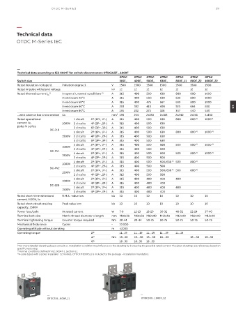
Technical data
OTDC M-Series IEC
—
Technical data according to IEC 60947 for switch-disconnectors OTDC315F…1000F
OTDC OTDC OTDC OTDC OTDC OTDC OTDC
Switch size 315F_ 400F_ 500F_ 630F_ 800F_11 800F_22 1000F_22
Rated insulation voltage U Pollution degree 3 V 1500 1500 1500 1500 1500 1500 1500
i
Rated impulse withstand voltage kV 12 12 12 12 12 12 12
Rated thermal current I th 1) In open air, normal conditions 2) A 315 400 500 630 800 800 1000
In enclosure 40°C A 315 400 500 630 630 800 1000
In enclosure 50°C A 315 400 475 567 630 800 1000
In enclosure 60°C A 293 352 415 498 523 664 830 05
In enclosure 80°C A 195 232 275 328 347 440 550
...with cable or bar cross section Cu mm² 185 240 2x150 2x185 2x240 2x241 4x150
Rated operational 1 circuit 2P (1P+, 1P-) A 315 400 500 630 800 800 3) 1000 3)
current Ie, 1000V 2 circuits 4P (2P+, 2P-) A 315 400 500 630
poles in series 3 circuits 6P (3P+, 3P-) A 315 400 500 630
DC-21B
1 circuit 2P (1P+, 1P-) A 315 400 500 630 800 800 3) 1000 3)
1500V 2 circuits 4P (2P+, 2P-) A 315 400 500 630
3 circuits 6P (3P+, 3P-) A 315 400 500 630
1 circuit 2P (1P+, 1P-) A 315 400 500 500 500 800 3) 1000 3)
1000V
DC-PV1 2 circuits 4P (2P+, 2P-) A A 315 400 500 500 500 800 3) 1000 3)
500
2P (1P+, 1P-)
315
400
500
1 circuit
1500V
2 circuits 4P (2P+, 2P-) A 315 400 500 500
1 circuit 2P (1P+, 1P-) A 315 400 500 500/630 3) 500 800 3)
1000V 2 circuits 4P (2P+, 2P-) A 315 400 500 500
DC-PV2 1 circuit 2P (1P+, 1P-) A 315 400 500 500/630 3) 500 800 3)
1500V
2 circuits 4P (2P+, 2P-) A 315 400 500 500
1 circuit 2P (1P+, 1P-) A 315 400 400 400 400
1000V 2 circuits 4P (2P+, 2P-) A 315 400 400 400
DC-22B 1 circuit 2P (1P+, 1P-) A 315 400 400 400 400
1500V
2 circuits 4P (2P+, 2P-) A 315 400 400 400
Rated short-time withstand R.M.S. -value Icw kA 10 10 10 10 10 10 10
current, 1500V, 1s
Rated short circuit making Peak value Icm kA 10 10 10 10 10 10 10
capacity, 1500V
Power loss/pole At rated current W 7-8 12-13 18-20 30-32 48-52 22-24 37-40
Terminal bolt size Metric thread diameter x length mm M10x30 M10x30 M12x40 M12x40 M12x40 M12x40 M12x40
Terminal tightening torque Counter torque required Nm 30-44 30-44 50-75 50-75 50-75 50-75 50-75
Mechanical Endurance Cycles - 10 000
Operating altitude without derating m ≤2000
Operating torque 2P 11...19 11…19 11…19 11…19 11...19
4P Nm 18...30 18…30 18…30 18…30 18…30 18...30
6P 18...35 18...35 18...35
1) For more detailed derating please consult us. Installation condition may influence on the derating by increasing the possible rated current. The given deratings are references based on
specific test setup.
2) Normal conditions defined in IEC 60947-1, section 6.1.
3) 4-pole-types with 2-poles in parallel _22 models, OTDCKIT800FS11 is included to the package – installation mandatory.
— —
OTDC315...800F_11 OTDC800...1000F_22