
Page 182 - 35_DS702_E_2014_Lightning_Protection_Guide
P. 182
6.3 Equipotential bonding for informa-
tion technology systems
Lightning equipotential bonding requires that all metal con-
ductive parts such as cable cores and shields at the entrance
point into the building be integrated in the equipotential
bonding system so as to cause as little impedance as possible.
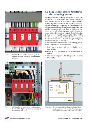
Examples of such parts include antenna lines (Figure 6.3.1),
tele communication lines with metal conductors and also opti-
cal fibre installations with metal elements. The lines are con-
nected with the help of lightning current carrying elements (ar-
resters and shield terminals). An adequate place of installation
is the point where the cabling extending beyond the building
transfers to cabling inside the building. Both the arresters and
the shield terminals must be chosen according to the lightning
current parameters to be expected.
In order to minimise induction loops within buildings, the fol-
lowing additional steps are recommended:
¨ Cables and metal pipes should enter the building at the
same location
¨ Power and data lines should be laid spatially close, but
shielded
Figure 6.2.1 DEHNbloc M for installation in conformity with the ¨ Unnecessarily long cables should be prevented by laying
lightning protection zone concept at the boundaries
from 0 A – 1 lines directly
α α
isolated air-termination system
with HVI Conductor
bare down
230 V~ conductor
DATA
230 V~
Figure 6.2.2 DEHNventil combined arrester for installation in con- Figure 6.3.1 Lightning equipotential bonding with an isolated air-ter-
formity with the lightning protection zone concept at mination system and a HVI Conductor for professional an-
the boundaries from 0 A – 2 tenna installations according to IEC 62305-3 (EN 62305-3)
www.dehn-international.com LIGHTNING PROTECTION GUIDE 181