
Page 180 - 35_DS702_E_2014_Lightning_Protection_Guide
P. 180
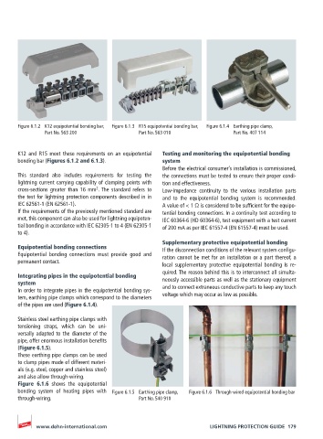
Figure 6.1.2  K12 equipotential bonding bar,   Figure 6.1.3  R15 equipotential bonding bar,   Figure 6.1.4  Earthing pipe clamp,
               Part No. 563 200              Part No. 563 010              Part No. 407 114


       K12 and R15 meet these requirements on an equipotential   Testing and monitoring the equipotential bonding
       bonding bar (Figures 6.1.2 and 6.1.3).       system
                                                    Before the electrical consumer’s installation is commissioned,
       This standard also includes requirements for testing the   the connections must be tested to ensure their proper condi-
       lightning current carrying capability of clamping points with   tion and effectiveness.
                               2
       cross-sections greater than 16 mm . The standard refers to   Low-impedance continuity to the various installation parts
       the test for lightning protection components described in in    and to the equipotential bonding system is recommended.
       IEC 62561-1 (EN 62561-1).                    A value of < 1 Ω is considered to be sufficient for the equipo-
       If the requirements of the previously mentioned standard are   tential bonding connections. In a continuity test according to
       met, this component can also be used for lightning equipoten-  IEC 60364-6 (HD 60364-6), test equipment with a test current
       tial bonding in accordance with IEC 62305-1 to 4 (EN 62305-1   of 200 mA as per IEC 61557-4 (EN 61557-4) must be used.
       to 4).
                                                    Supplementary protective equipotential bonding
       Equipotential bonding connections            If the disconnection conditions of the relevant system configu-
       Equipotential bonding connections must provide good and   ration cannot be met for an installation or a part thereof, a
       permanent contact.
                                                    local  supplementary  protective  equipotential  bonding  is  re-
                                                    quired. The reason behind this is to interconnect all simulta-
       Integrating pipes in the equipotential bonding
       system                                       neously accessible parts as well as the stationary equipment
       In order to integrate pipes in the equipotential bonding sys-  and to connect extraneous conductive parts to keep any touch
       tem, earthing pipe clamps which correspond to the diameters   voltage which may occur as low as possible.
       of the pipes are used (Figure 6.1.4).

       Stainless steel earthing pipe clamps with
       tensioning straps, which can be uni-
       versally adapted to the diameter of the
       pipe, offer enormous installation benefits
       (Figure 6.1.5).
       These earthing pipe clamps can be used
       to clamp pipes made of different materi-
       als (e.g. steel, copper and stainless steel)
       and also allow through-wiring.
       Figure 6.1.6 shows the equipotential
       bonding system of heating pipes with  Figure 6.1.5  Earthing pipe clamp,   Figure 6.1.6  Through-wired equipotential bonding bar
       through-wiring.                       Part No. 540 910


            www.dehn-international.com                             LIGHTNING PROTECTION GUIDE  179