
Page 184 - 35_DS702_E_2014_Lightning_Protection_Guide
P. 184
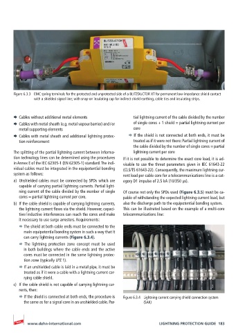
Figure 6.3.3  EMC spring terminals for the protected and unprotected side of a BLITZDUCTOR XT for permanent low-impedance shield contact
               with a shielded signal line; with snap-on insulating cap for indirect shield earthing, cable ties and insulating strips.


       ¨  Cables without additional metal elements       tial lightning current of the cable divided by the number
       ¨  Cables with metal sheath (e.g. metal vapour barrier) and / or   of single cores + 1 shield = partial lightning current per
         metal supporting elements                       core
       ¨  Cables with metal sheath and additional lightning protec-    ¨ If the shield is not connected at both ends, it must be
         tion reinforcement                              treated as if it were not there: Partial lightning current of
                                                         the cable divided by the number of single cores = partial
       The splitting of the partial lightning current between informa-  lightning current per core
       tion technology lines can be determined using the procedures   If it is not possible to determine the exact core load, it is ad-
       in Annex E of the IEC 62305-1 (EN 62305-1) standard. The indi-  visable to use the threat parameters given in IEC 61643-22
       vidual cables must be integrated in the equipotential bonding   (CLS/TS 61643-22). Consequently, the maximum lightning cur-
       system as follows:                           rent load per cable core for a telecommunications line is a cat-
       a)  Unshielded cables must be connected by SPDs which are   egory D1 impulse of 2.5 kA (10/350 μs).
         capable of carrying partial lightning currents. Partial light-
         ning current of the cable divided by the number of single   Of course not only the SPDs used (Figure 6.3.5) must be ca-
         cores = partial lightning current per core.  pable of withstanding the expected lightning current load, but
       b)  If the cable shield is capable of carrying lightning currents,   also the discharge path to the equipotential bonding system.
         the lightning current flows via the shield. However, capaci-  This can be illustrated based on the example of a multi-core
         tive / inductive interferences can reach the cores and make   telecommunications line:
         it necessary to use surge arresters. Requirements:
         ¨ The shield at both cable ends must be connected to the
           main equipotential bonding system in such a way that it
           can carry lightning currents (Figure 6.3.4).
         ¨ The lightning protection zone concept must be used
           in both buildings where the cable ends and the active
           cores must be connected in the same lightning protec-
           tion zone (typically LPZ 1).
         ¨ If an unshielded cable is laid in a metal pipe, it must be
           treated as if it were a cable with a lightning current car-
           rying cable shield.
       c)  If the cable shield is not capable of carrying lightning cur-
         rents, then:
         ¨ If the shield is connected at both ends, the procedure is   Figure 6.3.4  Lightning current carrying shield connection system
           the same as for a signal core in an unshielded cable. Par-  (SAK)


            www.dehn-international.com                             LIGHTNING PROTECTION GUIDE  183