
Page 183 - 35_DS702_E_2014_Lightning_Protection_Guide
P. 183
Antenna systems tric strength of the cable can be determined from the transfer
For reasons concerning radio communication, antenna systems impedance, the length of the antenna line and the amplitude
are generally mounted in an exposed location. Therefore, they of the lightning current.
are more affected by lightning currents and surges, especially
in the event of a direct lightning strike. In Germany they must According to the latest IEC 62305-3 (EN 62305-3) lightning
be integrated in the equipotential bonding system according protection standard, antenna systems on buildings can be pro-
to DIN VDE 0855-300 (German standard) and must reduce the tected by means of
risk of being affected by means of their design (cable struc- ¨ Air-termination rods
ture, connectors and fittings) or suitable additional measures. ¨ Elevated wires
Antenna elements that are connected to an antenna feeder
and cannot be connected directly to the equipotential bonding ¨ Or spanned cables.
system for functional reasons should be protected by lightning In each case, the separation distance s must be maintained.
current carrying arresters.
Expressed simply, it can be assumed that 50 % of the direct The electrical isolation of the lightning protection system from
lightning current flows away via the shields of all antenna conductive parts of the building structure (metal structural
lines. If an antenna system is dimensioned for lightning cur- parts, reinforcement etc.) and the isolation of the lightning
rents up to 100 kA (10/350 μs) (lightning protection level (LPL) protection system from electrical lines in the building prevent
III), the lightning current splits so that 50 kA flow through partial lightning currents from entering control and supply
the earthing conductor and 50 kA via the shields of all an- lines and thus prevent that sensitive electrical and electronic
tenna cables. Antenna systems which are not capable of devices are affected or destroyed (Figures 6.3.1 and 6.3.2).
carrying lightning currents must therefore be equipped with
air-termination systems in whose protected volume the anten- Optical fibre installations
nas are located. When choosing a suitable cable, the relevant Optical fibre installations with metal elements can normally be
partial lightning current ratio must be determined for each divided into the following types:
antenna line sharing the down conductor. The required dielec- ¨ Cables with metal-free core, but with metal sheath (e.g.
metal vapour barrier) or metal supporting elements
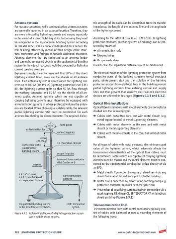
α α feed point ¨ Cables with metal elements in the core and with metal
air-termination tip sheath or metal supporting elements
connecting plate ¨ Cables with metal elements in the core, but without metal
sealing sheath.
end range
connection to the EB connection element For all types of cable with metal elements, the minimum peak
equipotential value of the lightning current, which adversely affects the
bonding system transmission characteristics of the optical fibre cables, must
supporting tube
be determined. Cables which are capable of carrying lightning
insulated down conductor currents must be chosen and the metal elements must be con-
(HVI Conductor I)
antenna nected to the equipotential bonding bar either directly or via
an SPD.
¨ Metal sheath: Connection by means of shield terminals e.g.
s = 0.75 m in air
^
s = 1.5 m in brickwork earth connection shield terminal at the entrance point into the building
^
element
s = separation distance ¨ Metal core: Connection by means of an earthing clamp e.g.
protective conductor terminal near the splice box
¨ Prevention of equalising currents: Indirect connection via a
spark gap e.g. DEHNgap CS, BLITZDUCTOR XT with indirect
shield earthing (Figure 6.3.3)
equipotential bonding system earth-termination Telecommunication lines
to the base transceiver station system
Telecommunication lines with metal conductors typically con-
Figure 6.3.2 Isolated installation of a lightning protection system sist of cables with balanced or coaxial stranding elements of
and a mobile phone antenna the following types:
182 LIGHTNING PROTECTION GUIDE www.dehn-international.com