
Page 262 - 35_DS702_E_2014_Lightning_Protection_Guide
P. 262
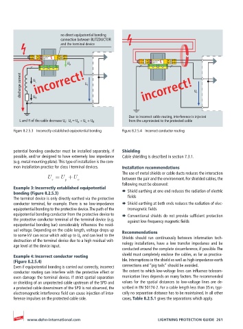
no direct equipotential bonding
                          connection between BLITZDUCTOR
                          and the terminal device


                2         2’  1’
                   BLITZDUCTOR
               1
                   BXT ML2 BD   4’  protected  3’
                   180
               3
                4
                                                                 BLITZDUCTOR  2’  1’
                                                            1
                                                              2
                                                                 BXT ML2 BD   4’  protected  3’
                                                              4
                                                            3
                             U p                                 180
          discharge current  U L incorrect!  U r             incorrect!            U r
               U R
                                                       Due to incorrect cable routing, interference is injected
         L and R of the cable decrease U r :  U r  = U p  + U L  + U R  from the unprotected to the protected cable
       Figure 8.2.5.3  Incorrectly established equipotential bonding  Figure 8.2.5.4  Incorrect conductor routing


       potential bonding conductor must be installed separately, if   Shielding
       possible, and / or designed to have extremely low impedance   Cable shielding is described in section 7.3.1.
       (e.g. metal mounting plate). This type of installation is the com-
       mon installation practice for class I terminal devices.  Installation recommendations
                                                    The use of metal shields or cable ducts reduces the interaction
                     U =U +U                        between the pair and the environment. For shielded cables, the
                       r    p     v
                                                    following must be observed:
       Example 3: Incorrectly established equipotential
       bonding (Figure 8.2.5.3)                     ¨  Shield earthing at one end reduces the radiation of electric
       The terminal device is only directly earthed via the protective   fields
       conductor terminal, for example. There is no low-impedance   ¨  Shield earthing at both ends reduces the radiation of elec-
       equipotential bonding to the protective device. The path of the   tromagnetic fields
       equipotential bonding conductor from the protective device to   ¨  Conventional shields do not provide sufficient protection
       the protective conductor terminal of the terminal device (e.g.   against low-frequency magnetic fields
       equipotential bonding bar) considerably influences the resid-
       ual voltage. Depending on the cable length, voltage drops up   Recommendations
       to some kV can occur which add up to U p  and can lead to the   Shields  should  run  continuously  between  information  tech-
       destruction of the terminal device due to a high residual volt-
       age level at the device input.               nology installations, have a low transfer impedance and be
                                                    conducted around the complete circumference, if possible. The
       Example 4: Incorrect conductor routing       shield must completely enclose the cables, as far as practica-
       (Figure 8.2.5.4)                             ble. Interruptions in the shield as well as high-impedance earth
       Even if equipotential bonding is carried out correctly, incorrect   connections and “pig tails“ should be avoided.
       conductor routing can interfere with the protective effect or   The extent to which low-voltage lines can influence telecom-
       even damage the terminal device. If strict spatial separation   munication lines depends on many factors. The recommended
       or shielding of an unprotected cable upstream of the SPD and   values for the spatial distances to low-voltage lines are de-
       a protected cable downstream of the SPD is not observed, the   scribed in EN 50174-2. For a cable length less than 35 m, typi-
       electromagnetic interference field can cause injection of inter-  cally no separation distance has to be maintained. In all other
       ference impulses on the protected cable side.  cases, Table 8.2.5.1 gives the separations which apply.


            www.dehn-international.com                             LIGHTNING PROTECTION GUIDE  261