
Page 261 - 35_DS702_E_2014_Lightning_Protection_Guide
P. 261
2
BLITZDUCTOR 2’ 1’ 1 2 BLITZDUCTOR 2’ 1’
1
BXT ML2 BD 4’ protected 3’ 3 4 BXT ML2 BD 4’ protected 3’
180 180
3
4
U p U p
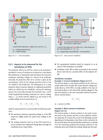
discharge current L of the cable U r discharge current L of the cable U v U r
R of the cable
R of the cable
e.g. protective conductor connection
of the power supply system
L and R of the cable have no effect on U r out of U r = U p L and R of the cable have little effect on U r , if the connection
U p = voltage protection level has a low impedance: U r = U p + U v
U r = residual voltage U v = voltage drop; connection BXT > terminal device
Figure 8.2.5.1 Correct installation Figure 8.2.5.2 Most common installation
8.2.5 Aspects to be observed for the ¨ The equipotential bonding should be designed so as to
installation of SPDs cause as little impedance as possible.
The protective effect of an SPD for a device to be protected is ¨ Installation of the SPD as close as possible to the terminal
provided if a source of interference is reduced to a value below device since this has a positive effect on the residual volt-
the interference or destruction limit and above the maximum age.
continuous operating voltage of a device to be protected. Installation examples
Generally, the protective effect of an arrester is given by the Example 1: Correct installation (Figure 8.2.5.1)
manufacturer in form of the voltage protection level U p (see The terminal device is only directly earthed via the earth con-
IEC 61643-21 (EN 61643-21)). The effectiveness of a surge nection point of the arrester. This means that the voltage pro-
protective device, however, depends on additional parameters tection level U p of the SPD is actually available at the input of
which are defined by the installation. During the discharge the terminal device in the form of the residual voltage U r . This
process, the current flow through the installation (e.g. L and R type of installation is the most favourable method for protect-
of the equipotential bonding conductor) can cause a voltage ing the terminal device.
drop U L + U R which must be added to U p and results in the
residual voltage at the terminal device U r : U =U p
r
U =U +U +U U L + U R have no effect.
r p L R
Optimal surge protection is ensured under the following condi- Example 2: Most common installation
tions: (Figure 8.2.5.2)
The terminal device is directly earthed via the earth connec-
¨ The maximum continuous operating voltage U c of the SPD tion point of the arrester and also via the protective conduc-
should be slightly above the open-circuit voltage of the tor connected. This means that a part of the discharge current,
system.
depending on the impedance ratio, flows via the connection to
¨ The voltage protection level U p of the SPD should be as the terminal device. To prevent that the interference is injected
low as possible since additional voltage drops through the from the connecting equipotential bonding conductor to the
installation have a lower effect. protected cores and to keep the residual voltage low, this equi-
260 LIGHTNING PROTECTION GUIDE www.dehn-international.com