
Page 288 - 35_DS702_E_2014_Lightning_Protection_Guide
P. 288
Lightning equipotential bonding for all conductive
α° 80 systems entering the sewage plant
70 In principle, all conductive systems entering the sewage plant
60 must be integrated in the lightning equipotential bonding
50 (Figure 9.4.4). This is achieved by directly connecting all met-
40 al systems and indirectly connecting all live systems via surge
protective devices. Type 1 SPDs (power supply systems) and
30 category D1 SPDs (information technology systems) must have
I II III IV
20 a discharge capacity of 10/350 μs test waveform. Lightning
10 equipotential bonding should be established as close as possi-
0 ble to the entrance point into the structure to prevent lightning
0 2 10 20 30 40 50 60 currents from entering the building.
h [m]
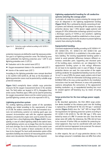
Figure 9.4.3 Protective angle method according to IEC 62305-3 Equipotential bonding
(EN 62305-3) Consistent equipotential bonding according to IEC 60364-4-41
(HD 60364-4-41), IEC 60364-5-54 (HD 60364-5-54) and
protection measures are defined to reach the necessary protec- IEC 62305-3 (EN 62305-3) is established in the entire opera-
tion goal in all lightning protection zones. The following areas tions building. The existing equipotential bonding system is
were subdivided into lightning protection zone 1 (LPZ 1) and tested to avoid potential differences between different ex-
lightning protection zone 2 (LPZ 2): traneous conductive parts. Supporting and structural parts
¨ Evaluation unit in the control room (LPZ 2) of the building, pipes, containers, etc. are integrated in the
equipotential bonding system so that voltage differences
¨ Oxygen measurement device in the aeration tank (LPZ 1) do not have to be expected, even in case of failure. If surge
¨ Interior of the control room (LPZ 1) protective devices are used, the cross-section of the copper
According to the lightning protection zone concept described earthing conductor for equipotential bonding must be at least
2
in IEC 62305-4 (EN 62305-4), all lines at the boundaries of 16 mm in case of SPDs for power supply systems and at least
2
lightning protection zones must be protected by suitable surge 6 mm in case of SPDs for information technology systems (e.g.
protection measures. BLITZDUCTOR) or the cross section specified in the installation
instructions must be used. Moreover, in areas with potentially
Figure 9.4.2 exemplarily shows suitable surge protection explosive atmospheres the connections of the equipotential
measures for the oxygen measurement device in the aeration bonding conductors e.g. at equipotential bonding bars must
tank. The field cables are located in LPZ 0 B throughout their be secured against self-loosening (e.g. by means of spring
entire course. Therefore, type 2 SPDs can be used for protecting washers).
the oxygen measurement device and the control systems since
(partial) lightning currents are not to be expected in LPZ 0 B . Surge protection for the low-voltage power supply
system
Lightning protection system In the described application, the VGA 280/4 surge protec-
The existing lightning protection system of the operations tive device installed at the entrance point into the building
building was tested according to the requirements of class is replaced by a DEHNventil M TNS 255 FM type 1 combined
of LPS III. The indirect connection of the roof-mounted struc- arrester (Figure 9.4.5) since the “old” SPD no longer fulfils
tures (air-conditioning systems) via isolating spark gaps was the requirements for lightning protection systems according to
removed. Air-termination rods with the required separation IEC 62305-3 (EN 62305-3). The VM 280 type 2 SPDs were
distances and protective angles were used to protect the sew- tested by means of a PM 10 arrester test unit. Since the test
age plant from a direct lightning strike (Figure 9.4.3). Conse- values were still within the tolerances, the SPDs did not have
quently, in case of a direct lightning strike to the control room, to be removed. If further SPDs are installed for protecting ter-
partial lightning currents can no longer flow into the structure minal equipment, they must be coordinated with each other
and cause damage. Due to the dimensions of the control room and with the terminal equipment to be protected. The relevant
(15 m x 12 m), the number of down conductors (4) did not installation instructions must be observed.
have to be changed. The local earth-termination system of the
operations building was tested at all measuring points and the In other respects, the use of surge protective devices in the
values were documented. Retrofitting was not required. low-voltage consumer's installation does not differ from other
www.dehn-international.com LIGHTNING PROTECTION GUIDE 287