
Page 292 - 35_DS702_E_2014_Lightning_Protection_Guide
P. 292
Nowadays conventional satellite and terrestrial antennas Earth-termination system
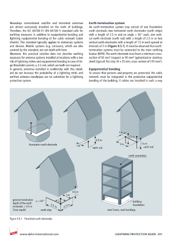
are almost exclusively installed on the roofs of buildings. An earth-termination system may consist of one foundation
Therefore, the IEC 60728-11 (EN 60728-1) standard calls for earth electrode, two horizontal earth electrodes (earth strips)
earthing measures in addition to equipotential bonding and with a length of 2.5 m and an angle > 60 ° each, one verti-
lightning equipotential bonding of the cable network (cable cal earth electrode (earth rod) with a length of 2.5 m or two
shields). This standard typically applies to stationary systems vertical earth electrodes with a length of 1.5 m each spaced at
and devices. Mobile systems (e.g. caravans), which are also intervals of 3 m (Figure 9.5.1). It must be observed that earth-
covered by the standard, are not dealt with here. termination systems must be connected to the main earthing
Moreover, this practical solution does not describe earthing busbar (MEB). The earth electrode must have a minimum cross-
2
2
measures for antenna systems installed at locations with a low section of 50 mm (copper) or 90 mm (galvanised or stainless
2
risk of lightning strikes and equipotential bonding in case of let- steel) (typical: flat strip 30 x 35 mm; cross-section of 105 mm ).
go threshold currents ≤ 3.5 mA, which are both not required.
In general, antennas installed in conformity with this stand- Equipotential bonding
ard do not increase the probability of a lightning strike and To ensure that persons and property are protected, the cable
earthed antenna standpipes are no substitute for a lightning network must be integrated in the protective equipotential
protection system. bonding of the building. If cables are installed in such a way
1 m
1.5 m
2.5 m
foundation earth electrode 1 m 3 m 1.5 m
earth rod earth rod
earth connection
0.5 m
1 m
general installation α > 60 ° α building
depth of the earth foundation
electrode: > 0.5 m 2.5 m 2.5 m
(frost depth) earth strip steel frame, steel buildings
Figure 9.5.1 Permitted earth electrodes
www.dehn-international.com LIGHTNING PROTECTION GUIDE 291