
Page 293 - 35_DS702_E_2014_Lightning_Protection_Guide
P. 293
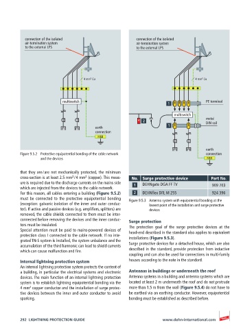
connection of the isolated                    connection of the isolated
            air-termination system                        air-termination system
            to the external LPS                           to the external LPS


                                       2
                                                                                      2
                                    4 mm  Cu                                       4 mm  Cu


                           multiswitch                                                 PE terminal


                                                                          multiswitch
                                                                                       metal
                                                                                       DIN rail
                                         earth
                                         connection
                                          MEB


                                                                                       earth
          Figure 9.5.2  Protective equipotential bonding of the cable network          connection
                  and the devices                                                       MEB

          that they are / are not mechanically protected, the minimum
                               2
                                     2
          cross-section is at least 2.5 mm  / 4 mm  (copper). This meas-  No.  Surge protective device  Part No.
          ure is required due to the discharge currents on the mains side   DEHNgate DGA FF TV  909 703
          which are injected from the devices to the cable network.
          For this reason, all cables entering a building (Figure 9.5.2)   DEHNflex DFL M 255  924 396
          must be connected to the protective equipotential bonding   Figure 9.5.3  Antenna system with equipotential bonding at the
          (exception: galvanic isolation of the inner and outer conduc-  lowest point of the installation and surge protective
          tor). If active and passive devices (e.g. amplifiers, splitters) are   devices
          removed, the cable shields connected to them must be inter-
          connected before removing the devices and the inner conduc-  Surge protection
          tors must be insulated.                      The protection goal of the surge protective devices at the
          Special attention must be paid to mains-powered devices of   head-end described in the standard also applies to equivalent
          protection class I connected to the cable network. If no inte-
          grated TN-S system is installed, the system unbalance and the   installations (Figure 9.5.3).
          accumulation of the third harmonic can lead to shield currents   Surge protective devices for a detached house, which are also
          which can cause malfunction and fire.        described in the standard, provide protection from inductive
                                                       coupling and can also be used for connections in multi-family
          Internal lightning protection system         houses according to the note in the standard.
          An internal lightning protection system protects the content of
          a building, in particular the electrical systems and electronic   Antennas in buildings or underneath the roof
          devices. The main function of an internal lightning protection   Antenna systems in a building and antenna systems which are
          system is to establish lightning equipotential bonding via the   located at least 2 m underneath the roof and do not protrude
             2
          4 mm  copper conductor and the installation of surge protec-  more than 1.5 m from the wall (Figure 9.5.4) do not have to
          tive devices between the inner and outer conductor to avoid   be earthed via an earthing conductor. However, equipotential
          sparking.                                    bonding must be established as described before.


          292  LIGHTNING PROTECTION GUIDE                            www.dehn-international.com