
Page 294 - 35_DS702_E_2014_Lightning_Protection_Guide
P. 294
≥ 2 m
protective angle
s
2
4 mm Cu
4 mm 2 Cu max. 1.5 m
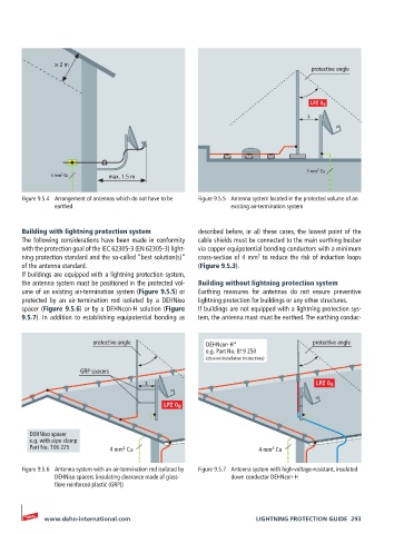
Figure 9.5.4 Arrangement of antennas which do not have to be Figure 9.5.5 Antenna system located in the protected volume of an
earthed existing air-termination system
Building with lightning protection system described before, in all these cases, the lowest point of the
The following considerations have been made in conformity cable shields must be connected to the main earthing busbar
with the protection goal of the IEC 62305-3 (EN 62305-3) light- via copper equipotential bonding conductors with a minimum
2
ning protection standard and the so-called “best solution(s)” cross-section of 4 mm to reduce the risk of induction loops
of the antenna standard. (Figure 9.5.3).
If buildings are equipped with a lightning protection system,
the antenna system must be positioned in the protected vol- Building without lightning protection system
ume of an existing air-termination system (Figure 9.5.5) or Earthing measures for antennas do not ensure preventive
protected by an air-termination rod isolated by a DEHNiso lightning protection for buildings or any other structures.
spacer (Figure 9.5.6) or by a DEHNcon-H solution (Figure If buildings are not equipped with a lightning protection sys-
9.5.7). In addition to establishing equipotential bonding as tem, the antenna mast must be earthed. The earthing conduc-
protective angle DEHNcon-H* protective angle
e.g. Part No. 819 250
(observe installation instructions)
GRP spacers
s
DEHNiso spacer
e.g. with pipe clamp
Part No. 106 225 4 mm Cu 4 mm Cu
2
2
Figure 9.5.6 Antenna system with an air-termination rod isolated by Figure 9.5.7 Antenna system with high-voltage-resistant, insulated
DEHNiso spacers (insulating clearance made of glass- down conductor DEHNcon-H
fibre reinforced plastic (GRP))
www.dehn-international.com LIGHTNING PROTECTION GUIDE 293