
Page 381 - 35_DS702_E_2014_Lightning_Protection_Guide
P. 381
Values for
Values for voltage-limiting voltage-switching or
Class of LPS or combined type 1 SPDs combined type 1 SPDs
and maximum (series connection) (parallel connection)
lightning current I 8/20
(10/350 µs) I 10/350 I 10/350
Per protective Per protective Per protective
path [kA] I total [kA] path [kA] I total [kA] path [kA] I total [kA]
III and IV 100 kA 5 10 15 30 10 20
Table 9.19.1 Minimum discharge capacity of voltage-limiting or combined type 1 SPDs and voltage-switching type 1 SPDs for free field
PV systems in case of LPL III; according to CENELEC CLC/TS 50539-12 (Table A.3)
Special surge protective devices for the d.c. side
of PV systems
The typical U/I characteristic curves of photovoltaic current
sources are very different from that of conventional d.c. sourc-
es: They have a non-linear characteristic (Figure 9.19.8) and a SCI SCI
different d.c. arc behaviour. This unique nature of photovoltaic
current sources does not only affect the design and size of PV
d.c. switches and PV fuses, but also requires that the surge
protective devices are adapted to this unique nature and capa-
ble of coping with PV d.c. follow currents. Supplement 5 of the
German DIN EN 62305-3 standard and the CENELEC CLC/TS
50539-12 standard require safe operation of surge protective
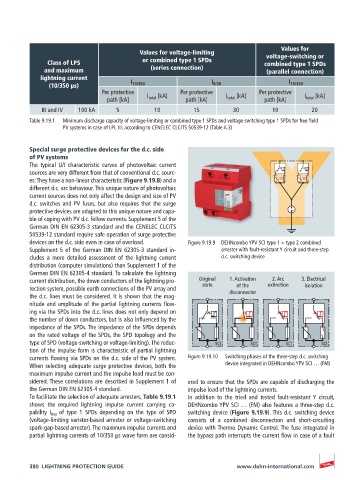
devices on the d.c. side even in case of overload. Figure 9.19.9 DEHNcombo YPV SCI type 1 + type 2 combined
Supplement 5 of the German DIN EN 62305-3 standard in- arrester with fault-resistant Y circuit and three-step
cludes a more detailed assessment of the lightning current d.c. switching device
distribution (computer simulations) than Supplement 1 of the
German DIN EN 62305-4 standard. To calculate the lightning
current distribution, the down conductors of the lightning pro- Original 1. Activation 2. Arc 3. Electrical
tection system, possible earth connections of the PV array and state of the extinction isolation
the d.c. lines must be considered. It is shown that the mag- disconnector
nitude and amplitude of the partial lightning currents flow-
ing via the SPDs into the d.c. lines does not only depend on
the number of down conductors, but is also influenced by the
impedance of the SPDs. The impedance of the SPDs depends
on the rated voltage of the SPDs, the SPD topology and the
type of SPD (voltage-switching or voltage-limiting). The reduc- SCI SCI SCI SCI
SCI
SCI
SCI
SCI
tion of the impulse form is characteristic of partial lightning
currents flowing via SPDs on the d.c. side of the PV system. Figure 9.19.10 Switching phases of the three-step d.c. switching
When selecting adequate surge protective devices, both the device integrated in DEHNcombo YPV SCI … (FM)
maximum impulse current and the impulse load must be con-
sidered. These correlations are described in Supplement 1 of ered to ensure that the SPDs are capable of discharging the
the German DIN EN 62305-4 standard. impulse load of the lightning currents.
To facilitate the selection of adequate arresters, Table 9.19.1 In addition to the tried and tested fault-resistant Y circuit,
shows the required lightning impulse current carrying ca- DEHNcombo YPV SCI … (FM) also features a three-step d.c.
pability I imp of type 1 SPDs depending on the type of SPD switching device (Figure 9.19.9). This d.c. switching device
(voltage-limiting varistor-based arrester or voltage-switching consists of a combined disconnection and short-circuiting
spark-gap-based arrester). The maximum impulse currents and device with Thermo Dynamic Control. The fuse integrated in
partial lightning currents of 10/350 µs wave form are consid- the bypass path interrupts the current flow in case of a fault
380 LIGHTNING PROTECTION GUIDE www.dehn-international.com