
Page 396 - 35_DS702_E_2014_Lightning_Protection_Guide
P. 396
earthing clamping points
conductor
depth in the ground
of at least 0.5 m
distance of at
least 0.5 m 1m 3m 3m 3m
protective angle
of max. 90 °
cable with current carrying shield
Figure 9.22.5 Protected volume for a cable route pylon
legs (step voltage) or may directly touch conductive structures Figure 9.22.6a Potential control on a pylon
(touch voltage). The resulting risk of injury can be reduced by
insulating the standing surface (standing surface insulation).
This measure reduces the risk of impermissibly high touch
and step voltages following a lightning strike. According to
IEC 62305 (EN 62305), an insulating asphalt layer of at least
5 cm around these parts is sufficient. As an alternative, CUI 0.5 m 1 m 1.5 m 2 m
Conductors with dielectric strengths ≥ 100 kV (1.2/50 µs) can
be used.
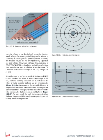
Potential control as per Supplement 1 of the German DIN EN
62305-3 standard also allows to reduce step voltages. To this
end, additional earthing conductors are buried around the 1 m 3 m 3 m 3 m
pylons or metal spectator galleries and are interconnected
(Figure 9.22.6a). Consequently, the potential difference in
the potential control area is reduced and the lightning current
U E
is evenly distributed in the ground. When the distance from the
pylon increases, the depth increases as well by 0.5 m (Figure
9.22.6b). The more evenly the earth electrodes are installed,
the lower the potential difference (step voltage). Thus, the risk Figure 9.22.6b Potential control on a pylon
of injury is considerably reduced.
www.dehn-international.com LIGHTNING PROTECTION GUIDE 395