
Page 447 - 35_DS702_E_2014_Lightning_Protection_Guide
P. 447
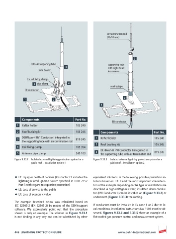
air-termination rod
                                                               (16/10 mm)


                   GRP / Al supporting tube                     supporting tube
                                                                with eight head-
                       tube holder                              less screws

                 2 x rail fixing clamps
                      pipe clamp
                                                                 sealing tape
               EB conductor


              Components                     Part No.
                                                                  EB conductor
              Rafter holder                  105 240
              Roof bushing kit               105 245       Components                     Part No.
              DEHNcon-H HVI Conductor I integrated in      Rafter holder                   105 240
              the supporting tube with air-termination rod  819 245
                                                           Roof bushing kit                105 245
              Rail fixing clamp              105 354
                                                           DEHNcon-H HVI Conductor I integrated in
              Antenna pipe clamp             540 103       the supporting tube with air-termination rod  819 245
          Figure 9.33.2  Isolated external lightning protection system for a   Figure 9.33.3  Isolated external lightning protection system for a
                   gable roof – Installation option 1            gable roof – Installation option 2


          ¨  L1: Injury or death of persons (loss factor L1 includes the   equivalent solutions. In the following, possible protection so-
            lightning-related ignition source specified in TRBS 2152   lutions based on LPL II and the most important characteris-
            Part 3 with regard to explosion protection)  tics of the example depending on the type of installation are
          ¨  L2: Loss of service to the public         described. A high-voltage-resistant, insulated down conduc-
          ¨  L4: Loss of economic value                tor (HVI Conductor I) can be installed on (Figure 9.33.2) or
                                                       underneath (Figure 9.33.3) the roofing.
          The example described below was calculated based on
          IEC 62305-2  (EN 62305-2) by means of  the DEHNsupport   If conductors must be installed in Ex zone 1 or 2 due to lo-
          software.  We expressively point out that the procedure   cal conditions, installation instructions No. 1501 must be ob-
          shown is only an example. The solution in Figure 9.33.1   served. Figures 9.33.4 and 9.33.5 show an example of a
          is not binding in any way and can be substituted by other   flat-roofed gas pressure control and measurement system.


          446  LIGHTNING PROTECTION GUIDE                            www.dehn-international.com