
Page 443 - 35_DS702_E_2014_Lightning_Protection_Guide
P. 443
Surge protective device
Technical data Transmitter TH02
BXT ML4 BD Ex 24
Place of installation zone 1 zone 1
Degree of protection ib ia
Voltage U i max. = 29.4 V d.c. U c = 33 V d.c.
Current I i max. = 130 mA I N = 500 mA
Frequency f HART = 2200 Hz, frequency modulated f G = 7.7 MHz
according to NE 21, discharge capacity of 20 kA (8/20 µs),
Immunity level
e.g. 0.5 kV core / core voltage protection level ≤ 52 V core / core
Tested to ATEX, CE ATEX, CE, IEC 6143-21, IECEX
Unearthed 500 V yes yes
C i =15 nF negligibly small
Internal capacitance C i
L i = 220 µH negligibly small
Internal capacitance L i
Table 9.32.2 Example of a temperature transmitter
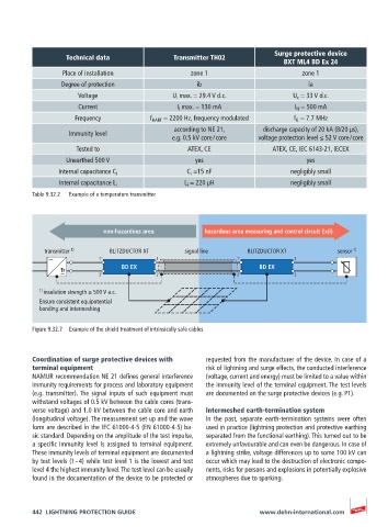
non-hazardous area hazardous area measuring and control circuit Ex(i)
transmitter 1) BLITZDUCTOR XT signal line BLITZDUCTOR XT sensor 1) 1)
sensor
1’ 1 1’ 1
Tr BD EX BD EX
2’ 2 2’ 2
1) insulation strength ≥ 500 V a.c.
Ensure consistent equipotential
bonding and intermeshing
Figure 9.32.7 Example of the shield treatment of intrinsically safe cables
Coordination of surge protective devices with requested from the manufacturer of the device. In case of a
terminal equipment risk of lightning and surge effects, the conducted interference
NAMUR recommendation NE 21 defines general interference (voltage, current and energy) must be limited to a value within
immunity requirements for process and laboratory equipment the immunity level of the terminal equipment. The test levels
(e.g. transmitter). The signal inputs of such equipment must are documented on the surge protective devices (e.g. P1).
withstand voltages of 0.5 kV between the cable cores (trans-
verse voltage) and 1.0 kV between the cable core and earth Intermeshed earth-termination system
(longitudinal voltage). The measurement set-up and the wave In the past, separate earth-termination systems were often
form are described in the IEC 61000-4-5 (EN 61000-4-5) ba- used in practice (lightning protection and protective earthing
sic standard. Depending on the amplitude of the test impulse, separated from the functional earthing). This turned out to be
a specific immunity level is assigned to terminal equipment. extremely unfavourable and can even be dangerous. In case of
These immunity levels of terminal equipment are documented a lightning strike, voltage differences up to some 100 kV can
by test levels (1 – 4) while test level 1 is the lowest and test occur which may lead to the destruction of electronic compo-
level 4 the highest immunity level. The test level can be usually nents, risks for persons and explosions in potentially explosive
found in the documentation of the device to be protected or atmospheres due to sparking.
442 LIGHTNING PROTECTION GUIDE www.dehn-international.com