
Page 1970 - Din prodcuts 2020
P. 1970
14/156 ELECTRICAL INSTALL ATION SOLUTIONS FOR BUILDINGS 2CHC 420 001 C0201
—
—
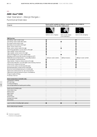
ABB i-bus® KNX
ABB i-bus® KNX
User Operation – Design Ranges –
User Operation – Design Ranges –
Functional Overview
Functional Overview
Busch-priOn® suitable for KNX bus coupler 6120/12-101 or 6120/13
Program
(depending on the specific combination)
6340-xx-101 1/2 gang 6341-xx-101 rotary 6342-xx-101 3/6 gang
control element
KNX function
Switching, rocker switch total ■ – ■
Switching, rocker switch left/right ■ ■ ■
Dimming, rocker switch total ■ – ■
Dimming, rocker switch left/right ■ – ■
Blind, rocker switch total ■ – ■
Blind, rocker switch total left/right ■ ■ ■
Short-long operation, rocker switch left/right ■ – ■
Value sender, rocker switch total ■ – ■
Value sender, rocker switch left/right ■ – ■
Value dimming sensor, rocker switch total ■ ■ ■
Red/green LED status illumination (red/green/off) – – –
RGB LED function illumination + status illumination 1 LED per rocker switch 1 LED per button 1 LED per rocker switch
Setting the RTC operating mode ■ – ■
Value sender, 2 objects, rocker switch left/right ■ – ■
Light scene extension unit with light scene memory function ■ – ■
Level switch, rocker switch total ■ – ■
Level switch, rocker switch total left/right ■ – ■
Multiple operation, rocker switch left/right ■ – ■
IR remote control channels (up to 13 channels) – – –
Light scene unit (8 scenes for up to 8 actuators) – – –
Light scene unit (10 scenes for up to 10 actuators) – – –
Programmable shift key – – –
Proximity function – – –
Room temperature controller only
Temperature reading – – –
RTC settings – – –
Illuminated display – – –
Fan coil operation for heating and cooling – – –
14
Media box/CD/DVD/radio – – –
Short-time timer – – –
Weekly timer – – –
Alarm clock – – –
Messages – – –
Screen saver – – –
Display text/value – – –
Device lock – – –
Logic function (including light scenes) ■ ■ ■
Busch-Watchdog 4 channels – – –
—
= Function is supported
– = Function is not supported