
Page 12 - SACE Tmax XT - Technical Catalogue
P. 12
1/8 SACE TMAX XT LOW VOLTAGE MOLDED CASE CIRCUIT-BREAKERS
—
Temperature performance
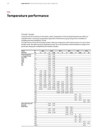
Power losses
To ensure service continuity of the plants, careful assessment of how to keep temperatures within ac-
ceptable levels is necessary to guarantee operation of all devices (e.g. by using forced ventilation in
switchboards and installation rooms).
The table below shows the dissipated power values per single pole at the rated current In for each circuit-
breaker used. The total maximum dissipated power for a circuit-breaker used at 50/60Hz is equal to the
power per single pole multiplied by the number of poles.
Power In XT1 XT2 XT3 XT4 XT5 XT6
[W/pole] [A] F P F P/W F P F P/W F P/W F W
Thermomagnetic 1.6 2.00 2.40
or magnetic only 2 2.40 2.80
trip unit:
TMD 2.5 2.50 2.80
TMA 3.2 2.80 3.20
TMG 4 2.50 2.80
MF 6.3 3.30 3.90
MA
8 2.60 3.00
10 2.90 3.40 2.00 2.20
12.5 1.00 1.20 2.30 2.40
16 1.50 1.60 1.30 1.50 2.50 2.60
20 1.80 2.00 1.60 1.90 2.60 2.70
25 2.00 2.80 2.00 2.5 2.70 2.80
32 2.10 3.20 2.60 3.00 4.40 4.50
40 2.60 4.60 3.70 4.40 4.50 4.70
50 3.70 5.00 4.10 4.70 4.70 4.90
63 4.30 6.00 4.80 5.70 4.30 5.10 5.30 5.70
80 4.80 7.20 5.80 6.80 4.80 5.80 5.50 6.10
100 7.00 10.00 8.10 9.50 5.60 6.80 6.20 7.20
125 10.70 14.70 11.40 14.00 6.60 7.90 7.40 9.00
160 15.00 16.10 19.00 7.90 9.50 8.90 10.80
200 13.20 15.80 11.90 14.90
250 17.80 21.40 16.40 21.10
320 16.9 23
400 24.1 33.6
500 33.5 45.8
630 47.8 67.3 34.4 42.5
800 54.2 67.7
Electronic trip unit: 10 0.10 0.10
Ekip Dip 25 0.80 0.90
Ekip Touch
40 0.60 0.70
63 1.70 2.10 1.40 1.80
100 4.20 5.20 3.50 4.50
160 10.80 13.40 8.90 11.50
250 16.40 22.70 8 11.7
320 11.6 17.7
400 19 27.6
500 28.3 40.6
630 45 64.5 33.2 41.5
800 53.4 66.7
1000 83.5