
Page 20 - SACE Tmax XT - Technical Catalogue
P. 20
1/16 SACE TMAX XT LOW VOLTAGE MOLDED CASE CIRCUIT-BREAKERS
—
Insulation distances
Installation of SACE Tmax XT
Minimum clearance between two superimposed circuit-breakers
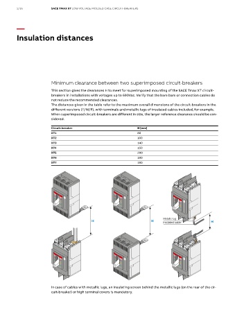
This section gives the clearances H to meet for superimposed mounting of the SACE Tmax XT circuit-
breakers in installations with voltages up to 690Vac. Verify that the bare bars or connection cables do
not reduce the recommended clearances.
The distances given in the table refer to the maximum overall dimensions of the circuit-breakers in the
Minimum clearance between two execution (F/W/P), with terminals and, for example, metallic
different versions (F/W/P), with terminals and metallic lugs of insulated cables included, for example.
superimposed circuit-breakers lugs of insulated cables included.
When superimposed circuit-breakers are different in size, the larger reference clearance should be con-
sidered. Circuit-breaker H [mm]
This section gives the clearances H to comply with for
superimposed mounting of SACE Tmax XT circuit-breakers in XT1 80
Circuit-breaker
H [mm]
installations with voltage up to 690Vac. 80 XT2 140
XT1
Verify that the bare bars or connection cables do not reduce XT3 140
XT2
100
the recommended clearances. 140 XT4 150
XT3
XT4 150 When the superimposed circuit-breakers are different in size
The distances given in the table are referred to the maximum (e.g. XT4 and XT2), the reference clearance to be considered
200
XT5
overall dimensions of the circuit-breakers in the different 180 is the longer one.
XT6
XT7 180
In case of cables with metallic lugs,
an insulating screen behind the
metallic lugs (on the rear of the cir-
cuit-breaker) or high terminal covers
are mandatory.
Metallic lug
H H H
Insulated cable
In case of cables with metallic lugs, an insulating screen behind the metallic lugs (on the rear of the cir-
cuit-breaker) or high terminal covers is mandatory.
6 SACE Tmax XT - Installation tips | ABB