Page 23 - SACE Tmax XT - Technical Catalogue
P. 23

INSTALL ATION                                                                    1/19
                                                                                                                       01

          —

          Special applications


                           Use of direct current apparatus

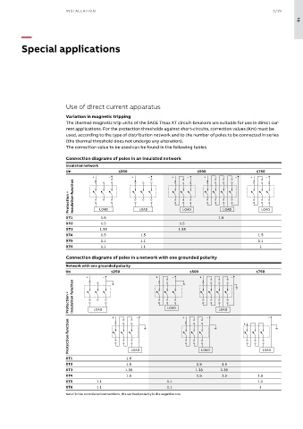
                           Variation in magnetic tripping
                           The thermal-magnetic trip units of the SACE Tmax XT circuit-breakers are suitable for use in direct cur-
                           rent applications. For the protection thresholds against short-circuits, correction values (Km) must be
                           used, according to the type of distribution network and to the number of poles to be connected in series
                           (the thermal threshold does not undergo any alteration).
                           The correction value to be used can be found in the following tables.
                           Connection diagrams of poles in an insulated network
                           Insulated network
                           Un                   ≤250                          ≤500                    ≤750
                                     +      –        +     –         +     –     +           –     +     –


                            Protection +   insulation function  LOAD  LOAD  LOAD         LOAD           LOAD


                           XT1           1.6                                           1.6
                           XT2           1.5                            1.5
                           XT3          1.35                           1.35
                           XT4           1.5            1.5                                           1.5
                           XT5           1.1            1.1                                           1.1
                           XT6           1.1            1.1                                            1
                           Connection diagrams of poles in a network with one grounded polarity

                           Network with one grounded polarity
                           Un                ≤250                           ≤500                      ≤750
                                   +     –                    +      –          +           –

                            Protection +   insulation function  LOAD     LOAD          LOAD


                                             +         –                 +        –              +        –
                            Protection function


                           XT1                     1.6 LOAD                     LOAD                    LOAD
                           XT2                     1.5                        1.5       1.5
                           XT3                    1.35                        1.35      1.35
                           XT4                     1.5                        1.5       1.5           1.5
                           XT5         1.1                         1.1                                1.1
                           XT6         1.1                         1.1                                 1
                           Note: in the considered connections, the earthed polarity is the negative one.
   18   19   20   21   22   23   24   25   26   27   28