
Page 21 - SACE Tmax XT - Technical Catalogue
P. 21
INSTALL ATION 1/17
01
The first insulated anchor
The first i nsu la t e d a n c h o r and t and to the cross-sectional area of the cable.
The first insulated anchor
o
h
c
The first insulated anchor
first
r
i
t
la
The
nsu
d
a
n
e
-
oss
s
e
ct
th
o
e
r
c
r
.
l
a
e
o
f the cable
a
na
io
.
e
io
f the cable
-
e
ct
s
a
o
l
e
oss
r
na
c
th
r
and to the cross-sectional area of the cable.
and t
o
a
r
c
i
cuit
T
ers SACE Tmax X
,
1
k
b
-
ea
r
ulded-case
For the moulded-case circuit-breakers SACE Tmax XT1,
e
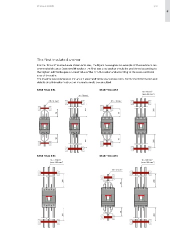
For th For the Tmax XT molded-case circuit-breakers, the figure below gives an example of the maximum rec- l l s s o w it h
mo
ers SACE Tmax X
T
mo
,
1
cuit
-
r
ulded-case
ea
k
b
r
The maximum
i
For the moulded-case circuit-breakers SACE Tmax XT1,
ended d
stance
For th
s valid a
i
m
e
The maximum recommended distance is valid also with
r
m
o
ec
i
c
it
ended d
stance
o
s valid a
The maximum recommended distance is valid also with
o
m
m
The maximum
h
i
ec
w
i
r
ommended distance (in mm) within which the first insulated anchor should be positioned according to
XT2, XT3 and XT4, the gure below gives an example of the
XT2, X T T 3 a a nd XT 4 4 , th e gu r r e b e e l l o w gives an example o f th e busbar connect io ns. For furth e e r i i nformat i i on and detail s
w gives an example
XT
o
o
3
e
b
XT2, X
e
gu
f th
nd
XT2, XT3 and XT4, the gure below gives an example of the
e
, th
busbar connections. For further information and details
on and detail
nformat
connect
io
s
r
busbar
ns. For furth
busbar connections. For further information and details
i
m
mu
maxi the highest admissible peak current value of the circuit-breaker and according to the cross-sectional
m
end
ch th
e
co
c
n
e
a
(in mm) within wh
r
e
d dist
m
e
e
c
end
reference must be made to the circuit-breaker technical
mu
maxi
m
d dist
e
a
n
maximum recommended distance (in mm) within which the reference must be made to the circuit-breaker technical
r
e
e
(in mm) within wh
co
ch th
m
i
m
maximum recommended distance (in mm) within which the reference must be made to the circuit-breaker technical
reference must be made to the circuit-breaker technical
area of the cable.
rst insu l l at e e d anchor sha l l l l b e positioned acco r r ding to th e catal og ues and i i nstruct i i on manu al s s . .
rst insulated anchor shall be positioned according to the
e
rst insu
positioned acco
b
e
rst insulated anchor shall be positioned according to the
ding to th
d anchor sha
at
catalogues and instruction manuals.
ues and
on manu
catal
nstruct
og
catalogues and instruction manuals.
al
The maximum recommended distance is also valid for busbar connections. For further information and
highest admissible peak current value of the circuit-breaker
highest a d m issible pe a a k c c ur r r ent v a a lue of the ci r r cuit-b r r eake r
k
ur
highest admissible peak current value of the circuit-breaker
issible pe
cuit-b
lue of the ci
a
r
d
v
eake
m
ent
highest
details circuit-breaker instruction manuals should be consulted.
SACE Tmax XT1
SACE Tmax XT2
SACE Tmax XT1 SACE Tmax XT2
SACE Tmax XT1
SACE Tmax XT2
SACE Tmax XT1
SACE Tmax XT2
SACE Tmax XT1 SACE Tmax XT2
16÷70 mm 2 2
16÷70 mm
16÷70 mm22
16÷70 mm
2
(max 95 mm
(max 95 mm )
(max 95 mm ) 22
16÷70 mm 2 2 (max 95 mm ) ) 2
16÷70 mm22
16÷70 mm
16÷70 mm
2.5÷10 mm 2 2 2.5÷10 mm 2 2
2.5÷10 mm22
2.5÷10 mm22
2.5÷10 mm
2.5÷10 mm
2.5÷10 mm
2.5÷10 mm
200 200 200 200 200 200 200 200
50 50 50 50 50 50 50 50
50 50 50 50 50 50 50 50
200 200 200 200 200 200 200 200
SACE Tmax XT3
SACE Tmax XT4
SACE Tmax XT3 SACE Tmax XT4
SACE Tmax XT3
SACE Tmax XT4
SACE Tmax XT3
SACE Tmax XT4
SACE Tmax XT4
SACE Tmax XT3
16÷120 mm 2 2 16÷120 mm 2 2
16÷120 mm22
16÷120 mm
16÷120 mm
16÷120 mm22
16÷120 mm
16÷120 mm
(max 185 mm ) ) 2 (max 185 mm ) ) 2
2
2
(max 185 mm )
(max 185 mm
(max 185 mm
(max 185 mm ) 22
(max 185 mm )
(max 185 mm ) 22
2.5÷10 mm 2 2
2.5÷10 mm22
2.5÷10 mm
2.5÷10 mm
200 200 200 200 200 200 200 200
50 50 50 50
50 50 50 50
200 200 200 200 200 200 200 200
(*) Value valid also with rear terminals
(*) Value valid also with rear terminals
(*) Value valid also with rear terminals
(*) Value valid also with rear terminals
ABB | SACE Tmax XT - Installation tips 7
ABB | SACE Tmax XT - Installation tips 7 Tmax XT - Installation tips
ABB | SACE Tmax XT - Installation tips 7 7
ABB | SACE