
Page 22 - SACE Tmax XT - Technical Catalogue
P. 22
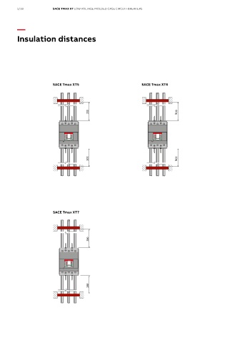
The first insulated anchor
and to the cross-sectional area of the cable.
and to the cross-sectional area of the cable.
For the moulded-case circuit-breakers SACE Tmax XT1,
For the moulded-case circuit-breakers SACE Tmax XT1,
The maximum recommended distance is valid also with
The maximum recommended distance is valid also with
XT2, XT3 and XT4, the gure below gives an example of the
XT2, XT3 and XT4, the gure below gives an example of th
e
busbar connections. For further information and details
busbar connections. For further information and details
e
maximum recommended distance (in mm) within which th
maximum recommended distance (in mm) within which the
reference must be made to the circuit-breaker technical
reference must be made to the circuit-breaker technical
e
rst insulated anchor shall be positioned according to th
rst insulated anchor shall be positioned according to the
catalogues and instruction manuals.
catalogues and instruction manuals.
highest admissible peak current value of the circuit-breaker
r
highest admissible peak current value of the circuit-breake
SACE Tmax XT1SACE Tmax XT2
SACE Tmax XT1
(max 95 mm 2 )
(max 95 mm 2 )
16÷70 mm 2
2.5÷10 mm 2
2.5÷10 mm 2 16÷70 mm 2 The first insulated anchor 16÷70 mm 2 SACE Tmax XT2 16÷70 mm 2
2.5÷10 mm 2
2.5÷10 mm 2
1/18 SACE TMAX XT LOW VOLTAGE MOLDED CASE CIRCUIT-BREAKERS
200 200 200 200
50 50 50 50
—
Insulation distances
50 50 50 50
200 200 200 200
The first insulated anchor
and to the cross-sectional area of the cable.
SACE Tmax XT3 SACE Tmax XT3SACE Tmax XT4 SACE Tmax XT4
For the moulded-case circuit-breakers SACE Tmax XT1, The maximum recommended distance is valid also with 16÷120 mm 2
16÷120 mm 2
16÷120 mm 2
16÷120 mm 2
SACE Tmax XT5
SACE Tmax XT6
XT2, XT3 and XT4, the gure below gives an example of the (max 185 mm 2 ) (max 185 mm 2 ) (max 185 mm 2 )
(max 185 mm 2 )
busbar connections. For further information and details
maximum recommended distance (in mm) within which the reference must be made to the circuit-breaker technical
rst insulated anchor shall be positioned according to the catalogues and instruction manuals. 2.5÷10 mm 2
2.5÷10 mm 2
highest admissible peak current value of the circuit-breaker
SACE Tmax XT1 200 SACE Tmax XT2 200 200 200
50 3 50
16÷70 mm 2
(max 95 mm 2 )
16÷70 mm 2
2.5÷10 mm 2 2.5÷10 mm 2
200 200
50 50
200 200 50 3 200 50 200
50
50
(*) Value valid also with rear terminals (*) Value valid also with rear terminals
200 200
SACE Tmax XT3 SACE Tmax XT4 ABB | SACE Tmax XT - Installation tips 7 ABB | SACE Tmax XT - Installation tips 7
16÷120 mm 2 16÷120 mm 2
SACE Tmax XT7 (max 185 mm 2 )
(max 185 mm 2 )
2.5÷10 mm 2
200 200
50
50
200 200
(*) Value valid also with rear terminals
ABB | SACE Tmax XT - Installation tips 7