
Page 18 - SACE Tmax XT - Technical Catalogue
P. 18
1/14 SACE TMAX XT LOW VOLTAGE MOLDED CASE CIRCUIT-BREAKERS
—
Insulation distances
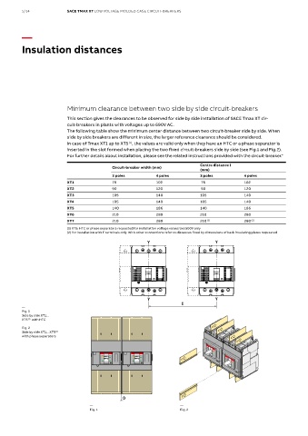
Minimum clearance between two side by side circuit-breakers
This section gives the clearances to be observed for side by side installation of SACE Tmax XT cir-
cuit-breakers in plants with voltages up to 690V AC.
The following table show the minimum center distance between two circuit-breaker side by side. When
side by side breakers are different in size, the larger reference clearance should be considered.
In case of Tmax XT1 up to XT5 , the values are valid only when they have an HTC or a phase separator is
(1)
inserted in the slot formed when placing the two fixed circuit-breakers side by side (see Fig.1 and Fig.2).
For further details about installation, please see the related instructions provided with the circuit-breaker."
Centre distance I
Circuit-breaker width (mm)
(mm)
3 poles 4 poles 3 poles 4 poles
XT1 76 102 76 102
XT2 90 120 90 120
XT3 105 140 105 140
XT4 105 140 105 140
XT5 140 186 140 186
XT6 210 280 210 280
XT7 210 280 210 (2) 280 (2)
(1) XT5: HTC or phase separators requested for installation voltage values Ue≥500V only
(2) for installation with F terminals only. With other connections refer to distances fixed by dimensions of back insulating plates requested
XT2 circuit-breakers, plug-in execution
with terminals EF, mounted side by side
— High terminal covers HTC Phase separators XT2 circuit-breakers, plug-in execution
Fig. 1 High terminal covers HTC Phase separators with terminals EF, mounted side by side
Side by side XT1…
XT5 (1) with HTC
Fig. 2
Side by side XT1…XT5 (1)
with phase separators
0
0
— —
Fig. 1 Fig. 2
If the conditions on page 4 are not complied with, SACE Circuit-breakers with front extended spread terminals ES
Tmax XT circuit-breakers can be installed side by side with a
minimum clearance D as shown in the following table:
D
D
If the conditions on page 4 are not complied with, SACE Circuit-breakers with front extended spread terminals ES
[mm]
Terminals
Circuit-breaker
Tmax XT circuit-breakers can be installed side by side with a
ES
35
XT1-XT3 F-P
minimum clearance D as shown in the following table:
35
EF
Other types of terminals 25 D
XT2-XT4 ES D 120
Terminals
Circuit-breaker F-W-P EF [mm] 35
35
XT1-XT3 F-P ES Other types of terminals 25
EF 35 D
Other types of terminals 25
ES
XT2-XT4 Here are some examples: 120
F-W-P Adjustable rear terminals R and low terminal covers LTC Circuit-breakers with front extended terminals EF
35
EF
Other types of terminals 25
D D
Here are some examples:
Adjustable rear terminals R and low terminal covers LTC Circuit-breakers with front extended terminals EF
D
D D
ABB | SACE Tmax XT - Installation tips 5
D
D
ABB | SACE Tmax XT - Installation tips 5