
Page 212 - 35_DS702_E_2014_Lightning_Protection_Guide
P. 212
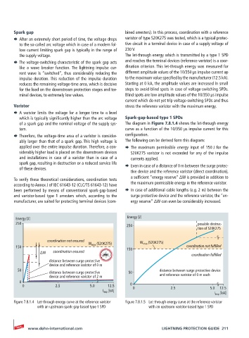
Spark gap                                    bined arresters). In this process, coordination with a reference
       ¨  After an extremely short period of time, the voltage drops   varistor of type S20K275 was tested, which is a typical protec-
         to the so-called arc voltage which in case of a modern fol-  tive circuit in a terminal device in case of a supply voltage of
         low current limiting spark gap is typically in the range of   230 V.
         the supply voltage.                        The let-through energy which is transmitted by a type 1 SPD
       ¨  The voltage-switching characteristic of the spark gap acts   and reaches the terminal devices (reference varistor) is a coor-
         like a wave breaker function. The lightning impulse cur-  dination criterion. This let-through energy was measured for
         rent wave is “switched”, thus considerably reducing the   different amplitude values of the 10/350 µs impulse current up
         impulse duration. This reduction of the impulse duration   to the maximum value specified by the manufacturer (12.5 kA).
         reduces the remaining voltage-time area, which is decisive   Starting at 0 kA, the amplitude values are increased in small
         for the load on the downstream protection stages and ter-  steps to avoid blind spots in case of voltage-switching SPDs.
         minal devices, to extremely low values.    Blind spots are low amplitude values of the 10/350 µs impulse
                                                    current which do not yet trip voltage-switching SPDs and thus
       Varistor                                     stress the reference varistor with the maximum energy.
       ¨  A varistor limits the voltage for a longer time to a level
         which is typically significantly higher than the arc voltage   Spark-gap-based type 1 SPDs
         of a spark gap and the nominal voltage of the supply sys-  The diagram in Figure 7.8.1.4 shows the let-through energy
         tem.                                       curve as a function of the 10/350 µs impulse current for this
       ¨  Therefore, the voltage-time area of a varistor is consider-  configuration.
         ably larger than that of a spark gap. This high voltage is   The following can be derived form this diagram:
         applied over the entire impulse duration. Therefore, a con-  ¨  The maximum permissible energy input of 150  J for the
         siderably higher load is placed on the downstream devices   S20K275 varistor is not exceeded for any of the impulse
         and installations in case of a varistor than in case of a   currents applied.
         spark gap, resulting in destruction or a reduced service life
         of these devices.                          ¨  Even in case of a distance of 0 m between the surge protec-
                                                       tive device and the reference varistor (direct coordination),
                                                       a sufficient “energy reserve” ∆W is provided in addition to
       To verify these theoretical considerations, coordination tests
       according to Annex J of IEC 61643-12 (CLC/TS 61643-12) have   the maximum permissible energy in the reference varistor.
       been  performed  by  means  of  conventional  spark-gap-based   ¨  In case of additional cable lengths (e.g. 2 m) between the
       and varistor-based type 1 arresters which, according to the   surge protective device and the reference varistor, the “en-
       manufacturer, are suited for protecting terminal devices (com-  ergy reserve” ∆W can even be considerably increased.


       Energy [J]                                    Energy [J]
       250                                                                        possible destruc-
                                                     250
                                                                                  tion of S20K275

                    coordination not ensured  W max  (S20K275)  W max  (S20K275)
       150                                           150                     coordination not fulfilled
                 ∆W    coordination ensured
                                                                                coordination fulfilled
                     distance between surge protective
                     device and reference varistor of 0 m
        50                                                        distance between surge protective device
                     distance between surge protective   50
                     device and reference varistor of 2 m         and reference varistor of 0 m each
         0
          0             2.5           5.0    12.5     0 0              2.5             5.0  12.5
                                           I imp  [kA]
                                                                                         I imp  [kA]
       Figure 7.8.1.4  Let-through energy curve at the reference varistor   Figure 7.8.1.5  Let-through energy curve at the reference varistor
                with an upstream spark-gap-based type 1 SPD   with an upstream varistor-based type 1 SPD


            www.dehn-international.com                             LIGHTNING PROTECTION GUIDE  211