
Page 214 - 35_DS702_E_2014_Lightning_Protection_Guide
P. 214
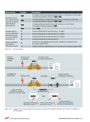
Characteristic    Symbol       Description
                                      D1 impulse (10/350 μs), lightning impulse current ≥ 2.5 kA / core or ≥ 5 kA / total
                                      • Exceeds the discharge capacity of     –
       Discharge capacity
       of an arrester (accord-        C2 impulse (8/20 μs), increased impulse load ≥ 2.5 kA / core or ≥ 5 kA / total
       ing to the categories            • Exceeds the discharge capacity of     –
       of IEC 61643-21                C1 impulse (8/20 μs), impulse load ≥ 0.25 kA / core or ≥ 0.5 kA / total
       (EN 61643-21))                   • Exceeds the discharge capacity of
                                      Load <
       Protective effect of           Test level required for the terminal device: 1 or higher
       an arrester (limitation        Test level required for the terminal device: 2 or higher
       below the test levels
       acc. to IEC 61000-4-5          Test level required for the terminal device: 3 or higher
       (EN 61000-4-5))                Test level required for the terminal device: 4
       Energy coordination            Arrester has a decoupling impedance and is suitable for coordination with
       (with another                  an arrester marked with
       Yellow/Line arrester)          Arrester suitable for coordination with an arrester with decoupling impedance
       Table 7.8.2.1  SPD class symbols


         use of a        lightning current   immunity test level
         combined        + overvoltage       according to EN 61000-4-5
         arrester
                                                        terminal
                                                        device
                                                                 1


         cascaded use                                              immunity test level
         of arresters   lightning current      overvoltage         according to EN 61000-4-5


                                                                                terminal
                                                                                device
                                                                                        1

              energy coordination
            of Yellow/Line arresters is     discharge capacity
          independent of the cable length


                                            +                        specific protection of
                            decoupling for coordination   arrester can be coordinated   terminal devices according to
                            with another arrester (       ) with another arrester (       +)  IEC 61000-4-5 (EN 61000-4-5)


       Figure 7.8.2.2  Examples of the energy-coordinated use of arresters according to the Yellow/Line SPD class and structure of the Yellow/Line
                SPD class symbol


            www.dehn-international.com                             LIGHTNING PROTECTION GUIDE  213