
Page 215 - 35_DS702_E_2014_Lightning_Protection_Guide
P. 215
standard impulse parameters and thus can be understood The surge protective devices of the Yellow/Line family are con-
from both a mathematical and a practical point of view. sistently and safely coordinated with one another and with the
The cascade according to Figure 7.8.2.1 is considered to be terminal devices. To this end, they are marked with the rel-
coordinated if the residual values I p in case of a short-circuited evant SPD class symbol (Tables 7.8.2.1 and 7.8.2.2, Figure
output and U p in case of an open-circuit output are smaller 7.8.2.2).
than the relevant input values I IN / U IN .
However, these methods are difficult to implement for the user
since they are very time-consuming. In order to save time and 7.9 Inspection and maintenance of the
work, the standard also allows to use the information provided LEMP protection measures system
by the manufacturer for coordination.
The fundamentals and prerequisites governing the inspection
A discharge capacity of 10/350 μs wave form is typically and maintenance of the LEMP protection measures system
specified for lightning current arresters installed at LPZ 0/1 or are the same as those governing the inspection and mainte-
higher. For surge arresters, in contrast, only a 8/20 μs wave nance of lightning protection systems as previously described
form is specified. This is due to the fact that surge arresters are in chapter 3.4.
mainly developed for inductively and capacitively coupled in- The inspections carried out during the construction phase are
particularly important for the inspection of the LEMP protec-
terference. If, however, a line extending beyond the building is
connected to a cascade comprising lightning current and surge tion measures system since many components of the LEMP
protection measures system are no longer accessible when the
arresters, the following can be concluded from the coordina- construction work has been completed. The necessary meas-
tion conditions:
ures (e.g. connection of the reinforcement) must be document-
¨ The most sensitive element (surge arrester) operates first ed with photos and included in the test report.
¨ The surge arrester must also be capable of carrying a part
of the partial lightning current of 10/350 μs wave form, al- Inspections should be carried out:
beit a low one ¨ During the installation of the LEMP protection measures
¨ Before the surge arrester is overloaded, the lightning cur- system
rent arrester must trip and take over the main portion of ¨ After the installation of the LEMP protection measures sys-
the discharge energy tem
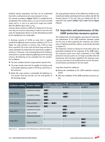
Exemplary assignment of SPD classes to LPZ transitions
Conductor routing Arrester solution
To LPZ 1 To LPZ 2 To LPZ 3
Combined arresters
From LPZ 0 A
Cascaded arresters
Combined arresters
From LPZ 0 B Surge arresters or
Cascaded arresters
Combined arresters –
From LPZ 1
Surge arresters – or
Combined arresters –
– –
From LPZ 2
Surge arresters – –
– –
Table 7.8.2.2 Assignment of the SPD classes to the LPZ transitions
214 LIGHTNING PROTECTION GUIDE www.dehn-international.com