
Page 211 - 35_DS702_E_2014_Lightning_Protection_Guide
P. 211
7.8 Coordination of the protection
measures at different LPZ
boundaries
7.8.1 Power supply systems
While surge protection in a device (or directly upstream of
it) fulfils the function of protecting the device, the surge pro-
tective devices in the surrounding installation have two func-
tions. On the one hand, they protect the installation, and, on
the other hand, they form the protective link between the
threat parameters of the complete system and the immunity
of the equipment and systems requiring protection. The threat
parameters of the system and the immunity of the device to
be protected are thus dimensioning factors for the protective
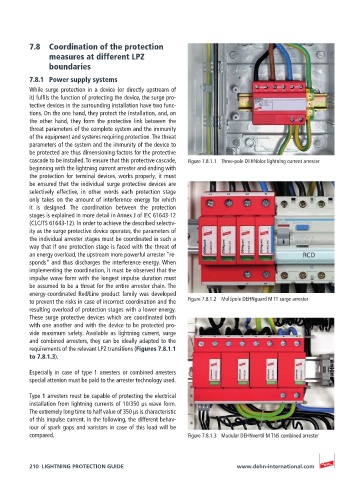
cascade to be installed. To ensure that this protective cascade, Figure 7.8.1.1 Three-pole DEHNbloc lightning current arrester
beginning with the lightning current arrester and ending with
the protection for terminal devices, works properly, it must
be ensured that the individual surge protective devices are
selectively effective, in other words each protection stage
only takes on the amount of interference energy for which
it is designed. The coordination between the protection
stages is explained in more detail in Annex J of IEC 61643-12
(CLC/TS 61643-12). In order to achieve the described selectiv-
ity as the surge protective device operates, the parameters of
the individual arrester stages must be coordinated in such a
way that if one protection stage is faced with the threat of
an energy overload, the upstream more powerful arrester “re-
sponds“ and thus discharges the interference energy. When
implementing the coordination, it must be observed that the
impulse wave form with the longest impulse duration must
be assumed to be a threat for the entire arrester chain. The
energy-coordinated Red/Line product family was developed
to prevent the risks in case of incorrect coordination and the Figure 7.8.1.2 Multipole DEHNguard M TT surge arrester
resulting overload of protection stages with a lower energy.
These surge protective devices which are coordinated both
with one another and with the device to be protected pro-
vide maximum safety. Available as lightning current, surge
and combined arresters, they can be ideally adapted to the
requirements of the relevant LPZ transitions (Figures 7.8.1.1
to 7.8.1.3).
Especially in case of type 1 arresters or combined arresters
special attenion must be paid to the arrester technology used.
Type 1 arresters must be capable of protecting the electrical
installation from lightning currents of 10/350 µs wave form.
The extremely long time to half value of 350 µs is characteristic
of this impulse current. In the following, the different behav-
iour of spark gaps and varistors in case of this load will be
compared. Figure 7.8.1.3 Modular DEHNventil M TNS combined arrester
210 LIGHTNING PROTECTION GUIDE www.dehn-international.com