
Page 213 - 35_DS702_E_2014_Lightning_Protection_Guide
P. 213
Coordination with the reference varistor is fully ensured over sufficiently low level due to the wave breaker function. The
the entire duration of the 10/350 µs impulse current under spark gap takes on almost the entire energy and the energy
consideration (information provided by the manufacturer: load on the downstream protection stages is only minimal.
I imp = 12.5 kV). This is not the case if a varistor-based type 1 SPD is used. The
ABB bulletin 19 by the German Committee for Lightning Pro-
Varistor-based type 1 SPDs tection and Lightning Research (ABB) at the VDE specifies that
Varistor-based type 1 SPDs are devices for which the manufac- general coordination is virtually excluded if voltage-limiting
turer specifies a maximum continuous operating voltage U C components (varistor) are used as type 1 SPD because the en-
of 280 V. This value is typically used in 230/400 V low-voltage ergy is not “switched”, but only limited. Since in case of doubt
systems. it can always be assumed that in a 230/400 V low-voltage sys-
The diagram in Figure 7.8.1.5 shows the let-through energy tem the protection stages and terminal devices are rated with
curve at the reference varistor for this type of device. 275 V, the energy load on them is considerably higher, which
The following can be derived form this diagram: may damage or destroy components or devices in the electrical
installation even in case of low lightning currents.
¨ It can be seen that the downstream reference varistor is en-
ergetically overloaded from about 2.5 kA (10/350 µs) and
may be destroyed from about 4 kA (10/350 µs).
7.8.2 Information technology systems
¨ In case of devices with a higher rated voltage (e.g.
U e = 335 V), energy overload and destruction may occur at When implementing measures to protect buildings against
even lower impulse current values due to the more unfa- interference from the effects of nearby, distant and direct
vourable impulse current distribution between the SPD and lightning strikes, it is recommended to use a multi-stage SPD
the reference varistor. concept. This reduces the high-energy interference (partial
lightning current) in stages since an initial upstream energy
¨ In comparison to the maximum specified impulse current absorbing stage prevents the main portion of the interference
of 12.5 kA, already extremely low impulse currents ener- from reaching the downstream system (wave breaker). The
getically overload the downstream protection stages or downstream stages reduce the interference to system-compat-
terminal devices. In practice, these components would be ible values. Depending on the installation conditions, several
pre-damaged or even destroyed. protection stages can also be integrated in a single surge pro-
tective device using a combined protective circuit (combined
The scenario of an additional cable length (2 m) between arrester). The relevant boundaries where the surge protective
the surge protective device and the reference varistor is not devices are installed in the form of a cascade are, for example,
described since there is almost no deviation from the values the zone boundaries (LPZ) of a lightning protection zone con-
shown due to the technology used. cept according to IEC 62305-4 (EN 62305-4).
The results described above clearly show that, without detailed Surge protective devices must be cascaded considering the
knowledge of the internal structure, a functioning energy co- coordination criteria.
ordination with downstream surge protective devices (type 2 Various methods are available to determine the coordination
and / or type 3) and terminal devices can only be achieved by conditions according to IEC 61643-22 (CLC/TS 61643-22),
means of spark-gap-based combined arresters (type 1 SPDs). some of which require special knowledge about the structure
The voltage-switching characteristic of the spark gap mitigates of the surge protective devices. A “black box” method is the
the incoming energy of the 10/350 µs lightning current to a so-called “let-through energy method”, which is based on
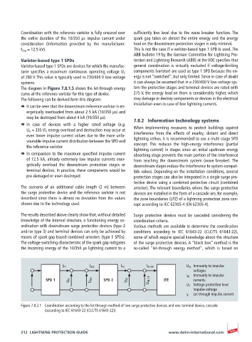
I P1 I IN2 I P2 I IN ITE U IN Immunity to impulse
voltages
I IN Immunity to impulse
SPD 1 U P1 U IN2 SPD 2 U P2 U IN ITE ITE currents
U P Voltage protection level
impulse voltage
I P Let-through impulse current
Figure 7.8.2.1 Coordination according to the let-through method of two surge protective devices and one terminal device, cascade
(according to IEC 61643-22 (CLC/TS 61643-22))
212 LIGHTNING PROTECTION GUIDE www.dehn-international.com