
Page 209 - 35_DS702_E_2014_Lightning_Protection_Guide
P. 209
Material Cross-section
Cu 6 mm 2
Al 10 mm 2
Fe 16 mm 2
Table 7.7.1.1 Minimum cross-sections for internal equipotential
bonding connections
7.7.2 Equipotential bonding for power supply
systems
LPZ 1 – LPZ 2 and higher
Surge limitation and field attenuation is also achieved for the
transitions from LPZ 1 to LPZ 2 and higher by systematically
Figure 7.7.1.1 Ring equipotential bonding and fixed earthing termi- integrating the electrical power supply and data lines in the
nal for the connection of metal installations equipotential bonding system at each LPZ transition in parallel
to all metal systems (Figure 7.7.2.1). Shielding the rooms and
devices attenuates the electromagnetic effect.
¨ Metal water supply pipes
The function of the surge protective devices used at the tran-
¨ Metal conduits for lines sitions from LPZ 1 to LPZ 2 or higher is to further minimise
¨ Other metal pipe systems or conductive parts (e.g. com- the residual values of upstream surge protective devices. They
pressed air) must reduce induced surges affecting the lines installed in the
The same cross-sections as described in chapter 6.2 must be LPZ and surges generated in the LPZ itself. The discharge ca-
used for the connecting cables of the equipotential bonding pacity of the SPDs which must be used can be derived from
bar leading to the earth-termination systems and other equi- Table E.2 of the IEC 62305-1 (EN 62305-1) standard. Type 2
potential bonding bars. SPDs should therefore be capable of discharging at least 5 kA
Reduced cross-sections can be used for these zone transitions (8/20 µs) per phase without destruction. Depending on the
to connect the metal installations to the equipotential bonding location where the protection measures are taken, they can
system (Table 7.7.1.1). be either assigned to a device (device protection) (Figure
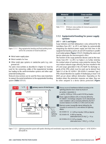
I 0 , H 0 primary source of interference Primary source of interference defined according to the
lightning protection level chosen by means of:
H 0
shield H 1 IEC 62305-1 (EN 62305-1):
I 0 and H 0 : 10/350 μs, 1/200 µs and 0.25/100 μs impulse
Power supply installation with an immunity defined by
shield H 2 IEC 60604-1: Overvoltage categories I to IV; telecommuni-
cation installation with an immunity defined by the ITU-T
recommendations K.20:2008, K.21:2003 and K.45:2003.
Electronic system (susceptible device) defined by the
electronic system immunity to conducted (U, I) and radiated (H) lightning
(susceptible effects:
device) U 2 , I 2 U 1 , I 1 U 0 , I 0
partial IEC 61000-4-5: U: 1.2/50 μs impulse, I: 8/20 μs impulse
shield (enclosure) lightning IEC 61000-4-9: H: 8/20 μs impulse,
current (attenuated wave 25 kHz), T p = 10 μs
IEC 61000-4-10: H: 0.2/5 μs impulse,
(attenuated wave 1 MHz), T p = 0.25 μs
Figure 7.7.2.1 Lightning protection system with spatial shielding and coordinated surge protection according to Figure A.1 of IEC 62305-4
(EN 62305-4)
208 LIGHTNING PROTECTION GUIDE www.dehn-international.com