
Page 218 - 35_DS702_E_2014_Lightning_Protection_Guide
P. 218
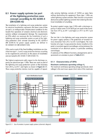
8.1  Power supply systems (as part           edly  carrying  lightning  currents  of  10/350  μs  wave  form
           of the lightning protection zone         without destructing the equipment. These type 1 SPDs are
                                                    called lightning current arresters. Their function is to prevent
           concept according to IEC 62305-4         destructive partial lightning currents from entering the elec-
           (EN 62305-4))                            trical installation of a building.
       The installation of a lightning and surge protection system
       for electrical installations represents the latest state of the   To protect against surges, type 2 SPDs with a discharge ca-
       art and is an indispensable infrastructural condition for the   pacity of about some 10 kA (8/20 μs) are used at the transi-
       trouble-free operation of complex electrical and electronic   tion from LPZ 0 B  to LPZ 1 and higher or LPZ 1 to LPZ 2 and
       systems without consequential damage. The requirements   higher.
       on SPDs which are necessary for the installation of such a
       lightning and surge protection system as part of the light-  The last link in the lightning and surge protection system
       ning protection zone concept according to IEC 62305-4   for power supply systems is the protection of terminal de-
       (EN  62305-4)  for  power  supply  systems  are  defined  in    vices (transition from LPZ 2 to LPZ 3 and higher). The main
       IEC 60364-5-53 (HD 60364-5-534).             function of a type 3 surge protective device installed at this
                                                    point is to protect against overvoltages arising between the
                                                    conductors of an electrical system, in particular switching
       SPDs used as part of the fixed building installation are clas-
       sified into type 1, 2 and 3 surge protective devices according   overvoltages.
       to the requirements and stress on the places of installation   A summary of the different functions, arrangements and re-
       and are tested to IEC 61643-11 (EN 61643-11).   quirements on arresters is given in Table 8.1.1.
       The highest requirements with respect to the discharge ca-
       pacity are placed on type 1 SPDs. These are used as part of   8.1.1  Characteristics of SPDs
       the lightning and surge protection system at the boundary   Maximum continuous operating voltage U c
       from LPZ 0 A  to LPZ 1 and higher as shown in Figure 8.1.1.   The maximum continuous operating voltage (previously: rated
       These surge protective devices must be capable of repeat-  voltage) is the root mean square (rms) value of the maximum


                   external LPS  lightning current arrester  sub-distribution board surge arrester  terminal devices
                            main distribution board


                            F1          meter
                                                                                         L1
                                                                                         L2
                                         Wh                                              L3
            PEN            SEB                                                           N
                                                                                         PE
                             F2                                      F3


                                      MEB                      local EBB


       Figure 8.1.1  Use of arresters in power supply systems (schematic diagram)


            www.dehn-international.com                             LIGHTNING PROTECTION GUIDE  217