
Page 223 - 35_DS702_E_2014_Lightning_Protection_Guide
P. 223
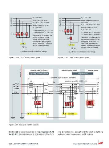
L1                   U 0  = 230 V a.c.        L1                  U 0  = 230 V a.c.
           L2                   Phase conductor to PE:   L2                  Phase conductor to neutral
           L3                   U c  ≥ 1.1 x 230 V = 253 V a.c.  L3          conductor:
           N                                             N                   U c  ≥ 1.1 x 230 V = 253 V a.c.
           PE                   Neutral conductor to PE:  PE
                                U c  ≥ 230 V a.c.                            Neutral conductor to PE:
                                3 x arrester with U c  ≥ 253 V a.c.  1.1 U 0  U c  ≥ 230 V a.c.
                                1 x arrester with U c  ≥ 230 V a.c.          3 x arrester with U c  ≥ 253 V a.c.
           1.1 U 0     U 0                                                   1 x arrester with U c  ≥ 230 V a.c.
                                The values of U 0  between the
                                neutral conductor and PE                     The values of U 0  between the
                                already refer to the most       U 0          neutral conductor and PE al-
                                unfavourable operating con-                  ready refer to the most un-
                                ditions. Therefore a tolerance               favourable operating con-
                                of 10 % is not considered.                   ditions. Therefore a tolerance
                         R A                                                 of 10 % is not considered.
                                                                      R A
                    U 0  = Phase-to-earth nominal a.c. voltage   U 0  = Phase-to-earth nominal a.c. voltage

          Figure 8.1.3.3a  “4 – 0” circuit in a TN-S system  Figure 8.1.3.3b  “3+1” circuit in a TN-S system


                     external  LPS  lightning current arrester  sub-distribution board  surge arrester terminal devices
                              main distribution board


                                                 protection as per IEC 62305 (EN 62305)
                             F1                               protection as per IEC 60364-4-443
                                                                                            L1
                                                                           RCD              L2
                                           Wh                                               L3
              PEN            SEB                                                            N
                                                                                            PE

                               F2                                      F3


                                       MEB                       local EBB


          Figure 8.1.3.4  SPDs used in a TN-C-S system


          trip the RCD or cause mechanical damage. Figures 8.1.3.5   ning protection zone concept and the resulting lightning
          to 8.1.3.11 illustrate the use of SPDs as part of the light-  and surge protection measures for TN systems.


          222  LIGHTNING PROTECTION GUIDE                            www.dehn-international.com