
Page 222 - 35_DS702_E_2014_Lightning_Protection_Guide
P. 222
Anforderungsklasse B) in Hauptstromversorgungssystemen.“
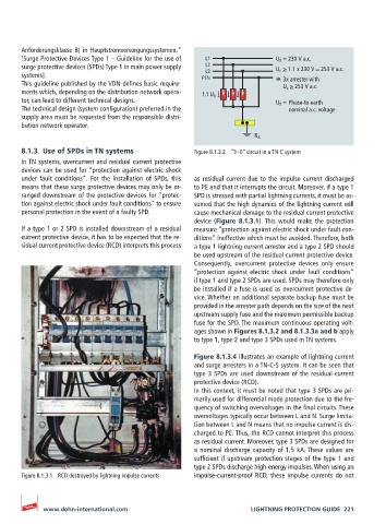
[Surge Protective Devices Type 1 – Guideline for the use of L1 U 0 = 230 V a.c.
surge protective devices (SPDs) Type 1 in main power supply L2 U c ≥ 1.1 x 230 V = 253 V a.c.
L3
systems]. PEN
This guideline published by the VDN defines basic require- 3x arrester with
U c ≥ 253 V a.c.
ments which, depending on the distribution network opera- 1.1 U 0
tor, can lead to different technical designs. U 0 = Phase-to-earth
The technical design (system configuration) preferred in the nominal a.c. voltage
supply area must be requested from the responsible distri-
bution network operator.
R A
8.1.3 Use of SPDs in TN systems Figure 8.1.3.2 “3 – 0” circuit in a TN-C system
In TN systems, overcurrent and residual current protective
devices can be used for “protection against electric shock
under fault conditions“. For the installation of SPDs, this as residual current due to the impulse current discharged
means that these surge protective devices may only be ar- to PE and that it interrupts the circuit. Moreover, if a type 1
ranged downstream of the protective devices for “protec- SPD is stressed with partial lightning currents, it must be as-
tion against electric shock under fault conditions” to ensure sumed that the high dynamics of the lightning current will
personal protection in the event of a faulty SPD. cause mechanical damage to the residual current protective
device (Figure 8.1.3.1). This would make the protection
If a type 1 or 2 SPD is installed downstream of a residual measure “protection against electric shock under fault con-
current protective device, it has to be expected that the re- ditions” ineffective which must be avoided. Therefore, both
sidual current protective device (RCD) interprets this process a type 1 lightning current arrester and a type 2 SPD should
be used upstream of the residual current protective device.
Consequently, overcurrent protective devices only ensure
“protection against electric shock under fault conditions”
if type 1 and type 2 SPDs are used. SPDs may therefore only
be installed if a fuse is used as overcurrent protective de-
vice. Whether an additional separate backup fuse must be
provided in the arrester path depends on the size of the next
upstream supply fuse and the maximum permissible backup
fuse for the SPD. The maximum continuous operating volt-
ages shown in Figures 8.1.3.2 and 8.1.3.3a and b apply
to type 1, type 2 and type 3 SPDs used in TN systems.
Figure 8.1.3.4 illustrates an example of lightning current
and surge arresters in a TN-C-S system. It can be seen that
type 3 SPDs are used downstream of the residual current
protective device (RCD).
In this context, it must be noted that type 3 SPDs are pri-
marily used for differential mode protection due to the fre-
quency of switching overvoltages in the final circuits. These
overvoltages typically occur between L and N. Surge limita-
tion between L and N means that no impulse current is dis-
charged to PE. Thus, the RCD cannot interpret this process
as residual current. Moreover, type 3 SPDs are designed for
a nominal discharge capacity of 1.5 kA. These values are
sufficient if upstream protection stages of the type 1 and
type 2 SPDs discharge high-energy impulses. When using an
Figure 8.1.3.1 RCD destroyed by lightning impulse currents impulse-current-proof RCD, these impulse currents do not
www.dehn-international.com LIGHTNING PROTECTION GUIDE 221