
Page 353 - 35_DS702_E_2014_Lightning_Protection_Guide
P. 353
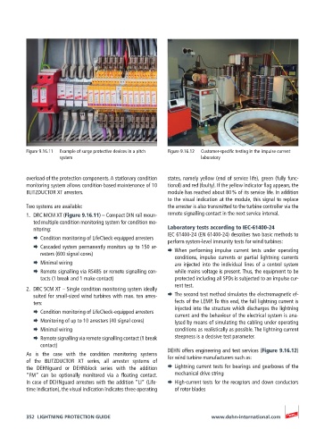
Figure 9.16.11   Example of surge protective devices in a pitch   Figure 9.16.12   Customer-specific testing in the impulse current
                    system                                        laboratory


          overload of the protection components. A stationary condition   states, namely yellow (end of service life), green (fully func-
          monitoring system allows condition-based maintenance of 10   tional) and red (faulty). If the yellow indicator flag appears, the
          BLITZDUCTOR XT arresters.                    module has reached about 80 % of its service life. In addition
                                                       to the visual indication at the module, this signal to replace
          Two systems are available:                   the arrester is also transmitted to the turbine controller via the
          1.  DRC MCM XT (Figure 9.16.11) – Compact DIN rail moun-  remote signalling contact in the next service interval.
            ted multiple condition monitoring system for condition mo-
            nitoring:                                  Laboratory tests according to IEC-61400-24
                                                       IEC 61400-24 (EN 61400-24) describes two basic methods to
            ¨  Condition monitoring of LifeCheck-equipped arresters  perform system-level immunity tests for wind turbines:
            ¨  Cascaded system permanently monitors up to 150 ar-  ¨  When performing impulse current tests under operating
              resters (600 signal cores)
                                                         conditions, impulse  currents  or  partial  lightning  currents
            ¨  Minimal wiring                            are injected into the individual lines of a control system
            ¨  Remote signalling via RS485 or remote signalling con-  while mains voltage is present. Thus, the equipment to be
              tacts (1 break and 1 make contact)         protected including all SPDs is subjected to an impulse cur-
                                                         rent test.
          2.  DRC SCM XT – Single condition monitoring system ideally
            suited for small-sized wind turbines with max. ten arres-  ¨  The second test method simulates the electromagnetic ef-
            ters:                                        fects of the LEMP. To this end, the full lightning current is
                                                         injected into the structure which discharges the lightning
            ¨  Condition monitoring of LifeCheck-equipped arresters  current and the behaviour of the electrical system is ana-
            ¨  Monitoring of up to 10 arresters (40 signal cores)  lysed by means of simulating the cabling under operating
            ¨  Minimal wiring                            conditions as realistically as possible. The lightning current
            ¨  Remote signalling via remote signalling contact (1 break    steepness is a decisive test parameter.
              contact)
                                                       DEHN offers engineering and test services (Figure 9.16.12)
          As  is  the  case  with  the  condition  monitoring  systems   for wind turbine manufacturers such as:
          of the BLITZDUCTOR XT series, all arrester  systems of
          the DEHNguard or DEHNblock series with the addition   ¨  Lightning current tests for bearings and gearboxes of the
          “FM”  can  be  optionally  monitored  via  a  floating  contact.    mechanical drive string
          In case of DEHNguard arresters with the addition “LI“ (Life-  ¨  High-current tests for the receptors and down conductors
          time Indication), the visual indication indicates three operating   of rotor blades


          352  LIGHTNING PROTECTION GUIDE                            www.dehn-international.com