
Page 351 - 35_DS702_E_2014_Lightning_Protection_Guide
P. 351
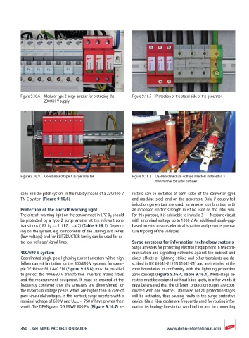
Figure 9.16.6  Modular type 2 surge arrester for protecting the   Figure 9.16.7  Protection of the stator side of the generator
                   230/400 V supply


          Figure 9.16.8  Coordinated type 1 surge arrester  Figure 9.16.9  DEHNmid medium-voltage arresters installed in a
                                                                 transformer for wind turbines

          celle and the pitch system in the hub by means of a 230/400 V   resters can be installed at both sides of the converter (grid
          TN-C system (Figure 9.16.6).                 and machine side) and on the generator. Only if doubly-fed
                                                       induction generators are used, an arrester combination with
          Protection of the aircraft warning light     an increased electric strength must be used on the rotor side.
          The aircraft warning light on the sensor mast in LPZ 0 B  should   For this purpose, it is advisable to install a 3 + 1 Neptune circuit
          be protected by a type 2 surge arrester at the relevant zone   with a nominal voltage up to 1000 V. An additional spark-gap-
          transitions (LPZ 0 B  → 1, LPZ 1 → 2) (Table 9.16.1). Depend-  based arrester ensures electrical isolation and prevents prema-
          ing on the system, e.g. components of the DEHNguard series   ture tripping of the varistors.
          (low voltage) and / or BLITZDUCTOR family can be used for ex-
          tra low voltage / signal lines.              Surge arresters for information technology systems
                                                       Surge arresters for protecting electronic equipment in telecom-
          400/690 V system                             munication and signalling networks against the indirect and
          Coordinated single-pole lightning current arresters with a high   direct effects of lightning strikes and other transients are de-
          follow current limitation for the 400/690 V systems, for exam-  scribed in IEC 61643-21 (EN 61643-21) and are installed at the
          ple DEHNbloc M 1 440 FM (Figure 9.16.8), must be installed   zone boundaries in conformity with the lightning protection
          to protect the 400/690 V transformer, inverters, mains filters   zone concept (Figure 9.16.4, Table 9.16.1). Multi-stage ar-
          and the measurement equipment. It must be ensured at the   resters must be designed without blind spots, in other words it
          frequency converter that the arresters are dimensioned for   must be ensured that the different protection stages are coor-
          the maximum voltage peaks, which are higher than in case of   dinated with one another. Otherwise not all protection stages
          pure sinusoidal voltages. In this context, surge arresters with a   will be activated, thus causing faults in the surge protective
          nominal voltage of 600 V and U mov  = 750 V have proven their   device. Glass fibre cables are frequently used for routing infor-
          worth. The DEHNguard DG M WE 600 FM (Figure 9.16.7) ar-  mation technology lines into a wind turbine and for connecting


          350  LIGHTNING PROTECTION GUIDE                            www.dehn-international.com