
Page 357 - 35_DS702_E_2014_Lightning_Protection_Guide
P. 357
External lightning protection
The antennas of the before mentioned systems are often in-
stalled on rented roof space. The antenna operator and the
building owner usually agree that the placement of anten-
nas must not present an additional risk for the building. For
the lightning protection system this means that no partial
lightning currents may enter the building in case of a light-
ning strike to the antenna tower since partial lightning cur-
rents inside the building would threaten the electrical and
electronic devices (Figure 9.17.2).
Figure 9.17.3 shows an antenna tower with an isolated
air-termination system.
The air-termination tip must be attached to the antenna
tower by means of a supporting tube made of non-conduc-
tive material. The height of the air-termination tip depends
on the antenna tower, possible electrical equipment of the
antenna system and the base station (RBS) and must be se-
lected in such a way that these elements are located in the
protected volume of the air-termination system. In case of
buildings with several antenna systems, several isolated air-
termination systems must be installed.
Radio base stations (RBS) with DEHNvap CSP
combined arresters
The power supply unit of the RBS must have a separate feed-
er cable that is independent from the power supply unit of
the building. A separate power sub-distribution board / floor
distributor should be provided for cell sites. Every sub-distri-
bution board is equipped with lightning and surge arresters
(type 1 combined arresters) as standard. In addition, a type 1
combined arrester is installed downstream of the meter
panel, namely downstream of the fuses. To ensure energy
coordination, surge protective devices (SPDs) from the same
manufacturer should be used at both places of installation.
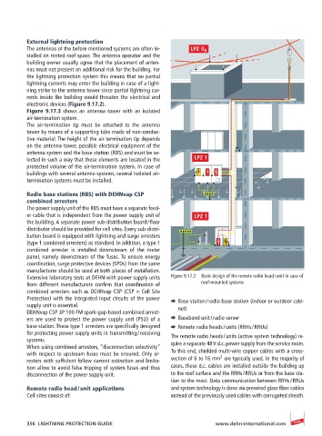
Extensive laboratory tests at DEHN with power supply units Figure 9.17.2 Basic design of the remote radio head / unit in case of
from different manufacturers confirm that coordination of roof-mounted systems
combined arresters such as DEHNvap CSP (CSP = Cell Site
Protection) with the integrated input circuits of the power ¨ Base station / radio base station (indoor or outdoor cabi-
supply unit is essential. net)
DEHNvap CSP 3P 100 FM spark-gap-based combined arrest-
ers are used to protect the power supply unit (PSU) of a ¨ Baseband unit / radio server
base station. These type 1 arresters are specifically designed ¨ Remote radio heads / units (RRHs / RRUs)
for protecting power supply units in transmitting / receiving The remote radio heads / units (active system technology) re-
systems. quire a separate 48 V d.c. power supply from the service room.
When using combined arresters, “disconnection selectivity”
with respect to upstream fuses must be ensured. Only ar- To this end, shielded multi-wire copper cables with a cross-
2
resters with sufficient follow current extinction and limita- section of 6 to 16 mm are typically used. In the majority of
tion allow to avoid false tripping of system fuses and thus cases, these d.c. cables are installed outside the building up
disconnection of the power supply unit. to the roof surface and the RRHs / RRUs or from the base sta-
tion to the mast. Data communication between RRHs / RRUs
Remote radio head / unit applications and system technology is done via prewired glass fibre cables
Cell sites consist of: instead of the previously used cables with corrugated sheath.
356 LIGHTNING PROTECTION GUIDE www.dehn-international.com