
Page 350 - 35_DS702_E_2014_Lightning_Protection_Guide
P. 350
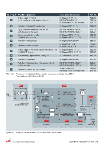
No. in Fig. 4 Area to be protected                Surge protective device      Part No.
                  Voltage supply of the hub               DEHNguard TN 275 FM          952 205
                  Signal lines between the nacelle and the hub  BLITZDUCTOR XT BE 24 *  920 324
                                                          DENHpatch DPA M CAT6 RJ45S48  929 121
                  Protection of the aircraft warning light  DEHNguard M TN 275 FM      952 205
                  Signal lines of the weather station and the  BLITZDUCTOR XT ML4 BE 24 *  920 324
                  control cabinet in the nacelle          BLITZDUCTOR XT ML2 BE S 24 *  920 224
                  Control cabinet in the nacelle          DEHNguard M TNC 275 FM       952 305
                  230/400 V voltage supply                DEHNguard M TNC CI 275 FM    952 309

                  Protection of the generator             DEHNguard M WE 600 FM        952 307
                                                          DEHNmid DMI 9 10 1           990 003
                  Protection of the transformer
                                                          DEHNmid DMI 36 10 1          990 013
                  Voltage supply of the control cabinet in the tower base,  DEHNguard M TNC 275 FM  952 305
                  230/400 V TN-C system                   DEHNguard M TNC CI 275 FM    952 309
                  Main incoming supply, 400/690 V TN system  3x DEHNbloc M 1 440 FM    961 145
                  Protection of the inverter              DEHNguard M WE 600 FM        952 307

                  Protection of the signal lines in the control cabinet    BLITZDUCTOR XT ML4 BE 24 *  920 324
                  of the tower base                       BLITZDUCTOR XT ML2 BE S 24 *  920 224
                                                          Air-termination rods         103 449
                  Protection of the nacelle superstructures
                                                          Pipe clamp for air-termination rods  540 105
       Table 9.16.1   Protection of a wind turbine (lightning protection zone concept according to Figure 9.16.4)
                * associated base part: BXT BAS, Part No. 920 300


               operation building                                            generator
                                                             shielded cable/   G
       high                                                 shielded cable route  3~
       voltage                           low-voltage
                                         switchgear
                                         installation                                  hub
                   shielded cable/
                                                             shielded cable/
                shielded cable route      power             shielded cable route
                                          electronics                         power supply
                                                                              control
                                                                              equipment
                                                             shielded cable/
                                    power supply            shielded cable route
                                    control equipment                      Top box
                                                                                       shielded
                                                                                        cable/
                                                                                       shielded
                                          tower base           tower       nacelle   cable route


       Figure 9.16.5  Example of arresters installed at the zone boundaries of a wind turbine


            www.dehn-international.com                             LIGHTNING PROTECTION GUIDE  349