
Page 360 - 35_DS702_E_2014_Lightning_Protection_Guide
P. 360
RRU 1 RRU 2 RRU 3
2
jumper cable 2 x 4 / 6 mm (shielded)
OVP, d.c. box (indoor) d.c. box (outdoor)
– 48 V
PSU
alarm cable
alarm cable
EB
2
NYCWY 2 x 16 mm (shielded)
Figure 9.17.4 Basic circuit diagram of remote radio heads (RRHs) in case of physically separated functional equipotential bonding levels with
d.c. box (outdoor) and DEHNsecure DSE M 2P 60 FM as well as with OVP box (indoor) and DEHNsecure DSE M 1 60 FM
rents up to max. 60 V d.c., no leakage currents and a high
degree of protection for terminal equipment due to the low
residual voltage of ≤ 0.4 kV at 5 kA (voltage protection level
of 1.5 kV (10/350 µs)).
Figure 9.17.4 shows the protection concept for RRHs / RRUs
in case of physically separated functional equipotential
bonding levels.
Type 1 combined arresters for RRH / RRU
installations
Figure 9.17.5 shows an example of a customised assembly
system with a spark-gap-based type 1 arrester according to
IEC 61643-1/11 (EN 61643-1/11).
The space-saving DEHNshield arrester with a width of only
two modules has a maximum discharge capacity of 12.5 kA
per pole (10/350 µs) and a voltage protection level U p of
1.5 kV and is thus ideally suited for protecting terminal
equipment. This assembly system allows to supply up to six
RRHs / RRUs with a nominal voltage of 48 V d.c. (max. 60 V
and max. 80 A) via glass fibre cables for data commu-
nication. Moreover, the design of the d.c. box ensures
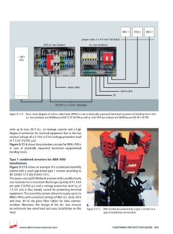
an extremely low wind load and easy installation on the Figure 9.17.5 RRH installation protected by a type 1 arrester in a
mast. typical installation environment
www.dehn-international.com LIGHTNING PROTECTION GUIDE 359