
Page 365 - 35_DS702_E_2014_Lightning_Protection_Guide
P. 365
insulation) as required in the IEC 60364-4-41 standard. The
metal substructure combination of numerous technologies on the module and
inverter side (e.g. with or without galvanic isolation) results
equipotential in different earthing requirements. Moreover, the insulation
bonding at least monitoring system integrated in the inverters is only perma-
2
6 mm Cu nently effective if the mounting system is connected to earth.
Information on the practical implementation is provided in
external lightning Supplement 5 of the German DIN EN 62305-3 standard. The
protection system; metal substructure is functionally earthed if the PV system is
separation distance located in the protected volume of the air-termination sys-
s is maintained
tems and the separation distance is maintained. Section 7
of Supplement 5 requires copper conductors with a cross-
2
section of at least 6 mm or equivalent for functional earthing
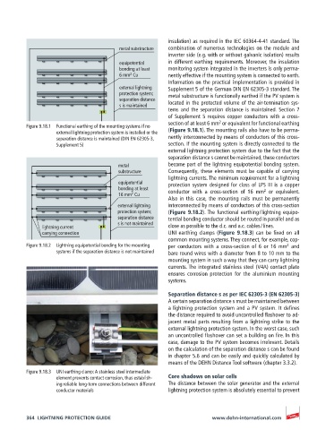
Figure 9.18.1 Functional earthing of the mounting systems if no
external lightning protection system is installed or the (Figure 9.18.1). The mounting rails also have to be perma-
separation distance is maintained (DIN EN 62305-3, nently interconnected by means of conductors of this cross-
Supplement 5) section. If the mounting system is directly connected to the
external lightning protection system due to the fact that the
separation distance s cannot be maintained, these conductors
metal become part of the lightning equipotential bonding system.
substructure Consequently, these elements must be capable of carrying
lightning currents. The minimum requirement for a lightning
equipotential protection system designed for class of LPS III is a copper
bonding at least conductor with a cross-section of 16 mm or equivalent.
2
2
16 mm Cu
Also in this case, the mounting rails must be permanently
external lightning interconnected by means of conductors of this cross-section
protection system; (Figure 9.18.2). The functional earthing / lightning equipo-
separation distance tential bonding conductor should be routed in parallel and as
s is not maintained
lightning current close as possible to the d.c. and a.c. cables / lines.
carrying connection UNI earthing clamps (Figure 9.18.3) can be fixed on all
common mounting systems. They connect, for example, cop-
Figure 9.18.2 Lightning equipotential bonding for the mounting per conductors with a cross-section of 6 or 16 mm and
2
systems if the separation distance is not maintained bare round wires with a diameter from 8 to 10 mm to the
mounting system in such a way that they can carry lightning
currents. The integrated stainless steel (V4A) contact plate
ensures corrosion protection for the aluminium mounting
systems.
Separation distance s as per IEC 62305-3 (EN 62305-3)
A certain separation distance s must be maintained between
a lightning protection system and a PV system. It defines
the distance required to avoid uncontrolled flashover to ad-
jacent metal parts resulting from a lightning strike to the
external lightning protection system. In the worst case, such
an uncontrolled flashover can set a building on fire. In this
case, damage to the PV system becomes irrelevant. Details
on the calculation of the separation distance s can be found
in chapter 5.6 and can be easily and quickly calculated by
means of the DEHN Distance Tool software (chapter 3.3.2).
Figure 9.18.3 UNI earthing clamp: A stainless steel intermediate
element prevents contact corrosion, thus establish- Core shadows on solar cells
ing reliable long-term connections between different The distance between the solar generator and the external
conductor materials lightning protection system is absolutely essential to prevent
364 LIGHTNING PROTECTION GUIDE www.dehn-international.com