
Page 441 - 35_DS702_E_2014_Lightning_Protection_Guide
P. 441
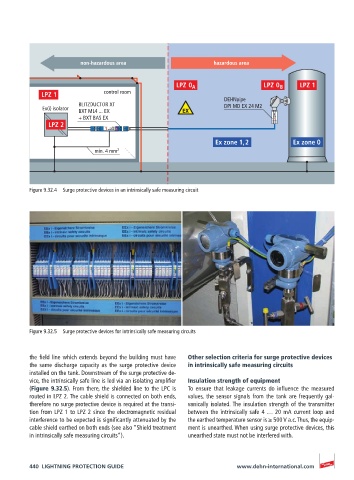
non-hazardous area                    hazardous area


                               control room
                                                                  DEHNpipe
                        BLITZDUCTOR XT                            DPI MD EX 24 M2
             Ex(i) isolator  BXT ML4 ... EX
                        + BXT BAS EX                                            FISCO
                            3’   4’  EX 24  BXT ML4 BD   4  3
                            1’  protected  2’  BLITZDUCTOR  2  1
                                                               Ex zone 1, 2          Ex zone 0
                            min. 4 mm 2


          Figure 9.32.4  Surge protective devices in an intrinsically safe measuring circuit


          Figure 9.32.5  Surge protective devices for intrinsically safe measuring circuits


          the field line which extends beyond the building must have   Other selection criteria for surge protective devices
          the  same  discharge  capacity  as  the  surge  protective  device   in intrinsically safe measuring circuits
          installed on the tank. Downstream of the surge protective de-
          vice, the intrinsically safe line is led via an isolating amplifier   Insulation strength of equipment
          (Figure 9.32.5). From there, the shielded line to the LPC is   To  ensure  that  leakage  currents  do  influence  the  measured
          routed in LPZ 2. The cable shield is connected on both ends,   values, the sensor signals from the tank are frequently gal-
          therefore no surge protective device is required at the transi-  vanically isolated. The insulation strength of the transmitter
          tion from LPZ 1 to LPZ 2 since the electromagnetic residual   between the intrinsically safe 4 … 20 mA current loop and
          interference to be expected is significantly attenuated by the   the earthed temperature sensor is ≥ 500 V a.c. Thus, the equip-
          cable shield earthed on both ends (see also “Shield treatment   ment is unearthed. When using surge protective devices, this
          in intrinsically safe measuring circuits”).  unearthed state must not be interfered with.


          440  LIGHTNING PROTECTION GUIDE                            www.dehn-international.com