
Page 64 - 35_DS702_E_2014_Lightning_Protection_Guide
P. 64
5.1 Air-termination systems ¨ Rolling sphere method
¨ Mesh method
The function of the air-termination systems of a lightning pro-
tection system is to prevent that direct lightning strikes dam- ¨ Protective angle method
age the volume to be protected. They must be designed to The rolling sphere method is the universal method of design
avoid uncontrolled lightning strikes to the building / structure particularly recommended for geometrically complicated ap-
to be protected. plications.
Correct dimensioning of the air-termination systems allows
to reduce the effects of a lightning strike to a structure in a The three different methods are described below.
controlled way.
Air-termination systems can consist of the following compo- 5.1.1 Types of air-termination systems and
nents and can be combined with each other as required:
design methods
¨ Rods Rolling sphere method – Electro-geometric model
¨ Spanned wires and cables For cloud-to-earth flashes, a downward leader grows step-
¨ Meshed conductors by-step in a series of jerks from the cloud towards the earth.
When determining the position of the air-termination systems When the downward leader has got close to the earth within
of the lightning protection system, special attention must be a few tens, to a few hundreds of metres, the electrical insula-
paid to the protection of corners and edges of the structure to tion strength of the air near the ground is exceeded. A further
be protected. This particularly applies to air-termination sys- “leader” discharge similar to the downward leader begins to
tems on the surfaces of roofs and the upper parts of façades. grow towards the head of the downward leader: The upward
Most importantly, air-termination systems must be mounted at leader. This defines the point of strike of the lightning strike
corners and edges. (Figure 5.1.1.1).
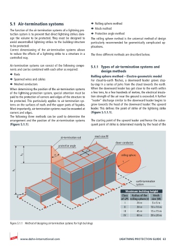
The following three methods can be used to determine the
arrangement and the position of the air-termination systems The starting point of the upward leader and hence the subse-
(Figure 5.1.1): quent point of strike is determined mainly by the head of the
air-termination rod mesh size M
down conductor
protective angle
h 2 α rolling sphere
r
h 1
earth-termination
system
Maximum building height
Class Radius of the Mesh
of LPS rolling sphere (r) size (M)
I 20 m 5 x 5 m
II 30 m 10 x 10 m
III 45 m 15 x 15 m
IV 60 m 20 x 20 m
Figure 5.1.1 Method of designing air-termination systems for high buildings
www.dehn-international.com LIGHTNING PROTECTION GUIDE 63