
Page 69 - 35_DS702_E_2014_Lightning_Protection_Guide
P. 69
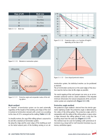
Class of LPS          Mesh size          α° 80
                    I                  5 x 5 m            70
                                                          60
                    II                10 x 10 m
                                                          50
                   III                15 x 15 m
                                                          40
                   IV                 20 x 20 m           30
          Table 5.1.1.3  Mesh size                        20             I     II      III     IV
                                                          10
                                                           0
                                          e.g. gutter       0 2   10    20   30    40   50    60
                                                                                             h [m]
                                                       Figure 5.1.1.12  Protective angle α as a function of height h
                                                                  depending on the class of LPS


                                                                         α°     α°
                                                         h 1
          Figure 5.1.1.10  Meshed air-termination system


            rolling sphere


                           r
                                                       Figure 5.1.1.13  Cone-shaped protected volume
             protective
                angle                                  termination system, the individual meshes can be positioned
             air-termi-   same  surface areas          as desired.
             nation rod                                The air-termination conductors on the outer edges of the struc-
                      α°                 ground area   ture must be laid as close to the edges as possible.

                                                       The metal capping of the roof parapet can serve as an air-ter-
          Figure 5.1.1.11  Protective angle and comparable radius of the roll-  mination conductor and / or a down conductor if the required
                    ing sphere                         minimum dimensions for natural components of the air-termi-
                                                       nation system are complied with (Figure 5.1.1.10).
          Mesh method                                  Protective angle method
          A “meshed” air-termination system can be used universally   The protective angle method is derived from the electric-geo-
          regardless of the height of the building and shape of the roof.   metric lightning model. The protective angle is determined by
          A meshed air-termination network with a mesh size according   the radius of the rolling sphere. The protective angle, which is
          to the class of LPS is arranged on the roofing (Table 5.1.1.3).  comparable with the radius of the rolling sphere, is given when
                                                       a slope intersects the rolling sphere in such a way that the
          To simplify matters, the sag of the rolling sphere is assumed to   resulting areas have the same size (Figure 5.1.1.11).
          be zero for a meshed air-termination system.  This method must be used for buildings with symmetrical di-
          By using the ridge and the outer edges of the building as well   mensions (e.g. steep roof) or roof-mounted structures (e.g. an-
          as the metal natural parts of the building serving as an air-  tennas, ventilation pipes).


          68  LIGHTNING PROTECTION GUIDE                             www.dehn-international.com