
Page 66 - 35_DS702_E_2014_Lightning_Protection_Guide
P. 66
Probabilities for the limits of the Radius of the rolling
Lightning Minimum peak value
protection level lightning current parameters sphere (final striking of current
LPL > minimum values < maximum values distance h B ) I in kA
r in m
IV 0.84 0.95 60 16
III 0.91 0.95 45 10
II 0.97 0.98 30 5
I 0.99 0.99 20 3
Table 5.1.1.1 Relation between lightning protection level, interception probability, final striking distance h B and minimum peak value of
current I; source: Table 5 of IEC 62305-1 (EN 62305-1)
any arrangement of objects to be investigated. A scale model on the model; it is also possible to determine the areas which
(e.g. on a scale of 1:100) of the object to be protected, which can be hit by side flashes. The naturally protected volumes re-
includes the external contours and, where applicable, the air- sulting from the geometry of the object to be protected and its
termination systems, is required to carry out the rolling sphere surroundings can also be clearly seen. Air-termination conduc-
method. Depending on the location of the object under inves- tors are not required at these points (Figure 5.1.1.3).
tigation, it is also necessary to include the surrounding build-
ings and objects since these could act as “natural protection However, it must be observed that lightning footprints have
measures” for the object under examination. also been found on steeples in places which were not directly
Furthermore, a true-to-scale sphere with a radius correspond- touched as the rolling sphere rolled over. This, among other
ing to the final striking distance (depending on the class of LPS, things, is due to the fact that in the event of multiple light-
the radius r of the rolling sphere must correspond true-to-scale ning strikes, the base of the lightning strike moves because of
to the radii 20, 30, 45 or 60 m) is required for the class of LPS. the wind conditions. Consequently, an area of approximately
The centre of the rolling sphere used corresponds to the head one metre can come up around the point of strike determined
of the downward leader towards which the respective upward where lightning strikes can also occur.
leaders will approach.
Example 1: New administration building in Munich
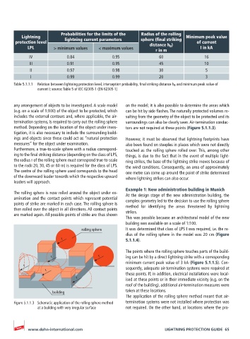
The rolling sphere is now rolled around the object under ex- At the design stage of the new administration building, the
amination and the contact points which represent potential complex geometry led to the decision to use the rolling sphere
points of strike are marked in each case. The rolling sphere is
then rolled over the object in all directions. All contact points method for identifying the areas threatened by lightning
are marked again. All possible points of strike are thus shown strikes.
This was possible because an architectural model of the new
building was available on a scale of 1:100.
rolling sphere It was determined that class of LPS I was required, i.e. the ra-
dius of the rolling sphere in the model was 20 cm (Figure
r 5.1.1.4).
The points where the rolling sphere touches parts of the build-
r r ing can be hit by a direct lightning strike with a corresponding
minimum current peak value of 3 kA (Figure 5.1.1.5). Con-
r
r sequently, adequate air-termination systems were required at
these points. If, in addition, electrical installations were local-
r ised at these points or in their immediate vicinity (e.g. on the
roof of the building), additional air-termination measures were
building taken at these locations.
The application of the rolling sphere method meant that air-
Figure 5.1.1.3 Schematic application of the rolling sphere method termination systems were not installed where protection was
at a building with very irregular surface not required. On the other hand, at locations where the pro-
www.dehn-international.com LIGHTNING PROTECTION GUIDE 65