
Page 70 - 35_DS702_E_2014_Lightning_Protection_Guide
P. 70
The protective angle depends on the class of LPS and the
height of the air-termination system above the reference plane
angle α (Figure 5.1.1.12).
Air-termination conductors, air-termination rods, masts and
wires should be arranged in such a way that all parts of the
structure to be protected are situated within the protected vol-
ume of the air-termination system.
angle α
The protected volume can be “cone-shaped” or “tent-shaped”,
if a cable, for example, is spanned over it (Figures. 5.1.1.13
to 5.1.1.15).
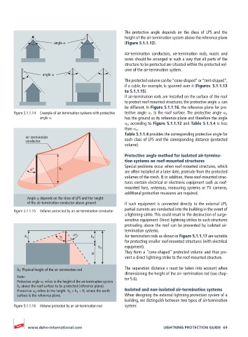
If air-termination rods are installed on the surface of the roof
to protect roof-mounted structures, the protective angle α can
be different. In Figure 5.1.1.16, the reference plane for pro-
Figure 5.1.1.14 Example of air-termination systems with protective tective angle α 1 is the roof surface. The protective angle α 2
angle α has the ground as its reference plane and therefore the angle
α 2 according to Figure 5.1.1.12 and Table 5.1.1.4 is less
than α 1 .
Table 5.1.1.4 provides the corresponding protective angle for
air-termination each class of LPS and the corresponding distance (protected
conductor
volume).
Protective angle method for isolated air-termina-
tion systems on roof-mounted structures
Special problems occur when roof-mounted structures, which
α° h 1
are often installed at a later date, protrude from the protected
volumes of the mesh. If, in addition, these roof-mounted struc-
tures contain electrical or electronic equipment such as roof-
mounted fans, antennas, measuring systems or TV cameras,
additional protection measures are required.
Angle α depends on the class of LPS and the height
of the air-termination conductor above ground If such equipment is connected directly to the external LPS,
Figure 5.1.1.15 Volume protected by an air-termination conductor partial currents are conducted into the building in the event of
a lightning strike. This could result in the destruction of surge-
sensitive equipment. Direct lightning strikes to such structures
protruding above the roof can be prevented by isolated air-
termination systems.
α 2 Air-termination rods as shown in Figure 5.1.1.17 are suitable
h 1 α 1 h 1
for protecting smaller roof-mounted structures (with electrical
equipment).
h 2
H They form a “cone-shaped” protected volume and thus pre-
vent a direct lightning strike to the roof-mounted structure.
h 1 : Physical height of the air-termination rod The separation distance s must be taken into account when
dimensioning the height of the air- termination rod (see chap-
Note: ter 5.6).
Protective angle α 1 refers to the height of the air-termination system
h 1 above the roof surface to be protected (reference plane).
Protective α 2 refers to the height h 2 = h 1 + H, where the earth Isolated and non-isolated air-termination systems
surface is the reference plane. When designing the external lightning protection system of a
building, we distinguish between two types of air-termination
Figure 5.1.1.16 Volume protected by an air-termination rod system:
www.dehn-international.com LIGHTNING PROTECTION GUIDE 69