
Page 96 - 35_DS702_E_2014_Lightning_Protection_Guide
P. 96
break and considerably affect the compensation effect in case ¨ The connections to conductive parts of the structure are
of a fall. This is impermissible. made wherever required.
Lightning protection
The rope of the safety rope system is part of a personal safety 5.2.1 Determination of the number of down
system and must not be used as an air-termination system! conductors
If lightning current is injected into the safety rope system, The number of down conductors depends on the perimeter of
the rope may be damaged by melting (reduced rope cross- the external edges of the roof (perimeter of the projection onto
section / reduced resistance). Therefore, the safety rope system the ground surface). The down conductors must be arranged
must be integrated in the external lightning protection system.
Figures 5.1.12.3 and 5.1.12.4 show the basic principle. to ensure that, starting at the corners of the structure, they are
The safety rope system is located in the protected volume of distributed as uniformly as possible to the perimeter.
Depending on the structural conditions (e.g. gates, precast
the air-termination rods. To implement equipotential bonding, components), the distances between the various down con-
an electrically safe connection is established at the intersec-
tions between the safety rope system and the lower air-termi- ductors can be different. In each case, there must be at least
nation mesh. the total number of down conductors required for the respec-
These connections must be capable of carrying lightning cur- tive class of LPS.
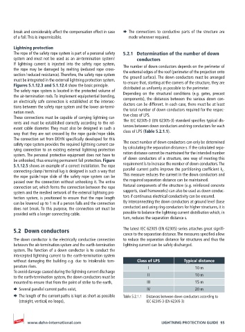
rents and must be established correctly according to the rel- The IEC 62305-3 (EN 62305-3) standard specifies typical dis-
evant cable diameter. They must also be designed in such a tances between down conductors and ring conductors for each
way that they are not crossed by the rope guide / rope slide. class of LPS (Table 5.2.1.1).
The connection set from DEHN specifically developed for this
safety rope system provides the required lightning current car- The exact number of down conductors can only be determined
rying connection to an existing external lightning protection by calculating the separation distance s. If the calculated sepa-
system. The personal protective equipment does not have to ration distance cannot be maintained for the intended number
be unhooked, thus ensuring permanent fall protection. Figure of down conductors of a structure, one way of meeting this
5.1.12.5 shows an example of a correct installation. The rope requirement is to increase the number of down conductors. The
connecting clamp / terminal lug is designed in such a way that parallel current paths improve the partitioning coefficient k c .
the rope guide / rope slide of the safety rope system can be This measure reduces the current in the down conductors and
passed over the connection without unhooking it. The entire the required separation distance can be maintained.
connection set, which forms the connection between the rope Natural components of the structure (e.g. reinforced concrete
system and the meshed network of the external lightning pro- supports, steel frameworks) can also be used as down conduc-
tection system, is positioned to ensure that the rope length tors if continuous electrical conductivity can be ensured.
can be lowered up to 1 m if a person falls and the connection By interconnecting the down conductors at ground level (base
does not break. To this purpose, the connection set must be conductor) and using ring conductors for higher structures, it is
provided with a longer connecting cable. possible to balance the lightning current distribution which, in
turn, reduces the separation distance s.
5.2 Down conductors The latest IEC 62305 (EN 62305) series attaches great signifi-
cance to the separation distance. The measures specified allow
The down conductor is the electrically conductive connection to reduce the separation distance for structures and thus the
between the air-termination system and the earth-termination lightning current can be safely discharged.
system. The function of a down conductor is to conduct the
intercepted lightning current to the earth-termination system
without damaging the building e.g. due to intolerable tem- Class of LPS Typical distance
perature rises. I 10 m
To avoid damage caused during the lightning current discharge
to the earth-termination system, the down conductors must be II 10 m
mounted to ensure that from the point of strike to the earth, III 15 m
¨ Several parallel current paths exist, IV 20 m
¨ The length of the current paths is kept as short as possible Table 5.2.1.1 Distances between down conductors according to
(straight, vertical, no loops), IEC 62305-3 (EN 62305-3)
www.dehn-international.com LIGHTNING PROTECTION GUIDE 95