
Page 93 - 35_DS702_E_2014_Lightning_Protection_Guide
P. 93
¨ Material characteristics
The performance of the material is determined by the cross-
sectional values, modulus of elasticity, density and lateral
contraction.
¨ Loads
The wind load is applied to the geometric model in the form
of a pressure load.
The break resistance is determined by comparing the permis-
sible bending stress (material property) and the maximum
bending stress (calculated from the bending moment and the
effective cross-section at the point of maximum stress).
Break resistance is achieved if the ratio between the permis-
sible and the actual bending stress is > 1. Basically, the same
also applies in this case: The greater the ratio between the
permissible and the actual bending stress, the greater is the
break resistance.
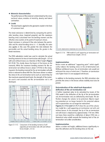
Figure 5.1.11.6 FEM model of a self-supporting air-termination rod
without brace (length = 8.5 m)
The FEM calculation model was used to calculate the actual
bending moments for two air-termination rods (length = 8.5 m)
with and without braces as a function of their height (Figure
5.1.11.5). This clearly shows the impact of the braces on the Implementation
moments. While the maximum bending moment for the air- Braces create an additional “supporting point” which signifi-
termination rod without brace is about 1270 Nm in the clamp- cantly reduces the bending stress in the air-termination rod.
ing point, the bending moment for the air-termination rod with Without additional braces, the air-termination rods would not
withstand the stress of wind zone 2. Therefore, air-termination
brace is reduced to about 460 Nm. This brace allows to reduce rods higher than 6 m are equipped with braces.
the stress in the air-termination rod to such an extent that, for
the maximum expected wind loads, the strength of the materi- In addition to the bending moments, the FEM calculation also
als used is not exceeded and the air-termination rod is not provides the stress in the braces whose stability must also be
destroyed.
proven.
Determination of the wind-load-dependent
deflection of the air-termination rod
A further important value to be calculated by means of the
FEM model is the deflection of the tip of the air-termination
rod. Air-termination rods are deflected by wind loads. This de-
flection changes the volume to be protected. Objects requir-
ing protection are no longer located in the protected volume
and / or proximities can no longer be maintained.
Figures 5.1.11.6 and 5.1.11.7 show the use of the calcula-
tion model for a self-supporting air-termination rod with and
without braces. In this example, the tip of the air-termination
rod with brace is displaced by approximately 1150 mm. With-
out brace there would be a deflection of about 3740 mm, a
theoretical value which exceeds the breaking limit of the air-
termination rod under consideration.
Figure 5.1.11.5 Comparison of the bending moments of self- Implementation
supporting air-termination rods with and without Above a certain rod height, additional braces significantly re-
braces (length = 8.5 m) duce this defection and the bending stress on the rod.
92 LIGHTNING PROTECTION GUIDE www.dehn-international.com