
Page 97 - 35_DS702_E_2014_Lightning_Protection_Guide
P. 97
If these measures are not sufficient to maintain the required an additional PVC sheath or PVC-sheathed aluminium wire is
separation distance, high voltage-resistant, insulated conduc- used.
tors (HVI Conductors) can also be used as an alternative. These If the wall is made of highly combustible material and the tem-
are described in chapter 5.2.4. perature rise of the down conductors presents a hazard, the
Chapter 5.6 describes how to exactly determine the separation down conductors must be mounted in such a way that the
distance. distance between the down conductors and the wall is greater
than 0.1 m. The fixing elements may touch the wall. The in-
staller of the structure must specify whether the wall on which
5.2.2 Down conductors for a non-isolated a down conductor is to be installed is made of combustible
lightning protection system material.
Down conductors are primarily mounted directly onto the In Germany the terms flame-resistant, normally inflammable
building (without separation distance). The reason for install- and highly combustible are exactly defined in Annex E.101
ing them directly onto the structure is the temperature rise in of Supplement 1 of the DIN EN 62305-3 (VDE 0185-305-3)
the event of lightning striking the lightning protection system. standard.
If the wall is made of flame-resistant or normally inflammable
material, the down conductors may be installed directly on or
in the wall. 5.2.2.1 Installation of down conductors
Owing to the specifications in the building regulations of the The down conductors must be arranged in such a way that
German federal states, highly combustible materials are gener- they are the direct continuation of the air-termination conduc-
ally not used. This means that down conductors can usually be tors. They must be installed vertically in a straight line so that
mounted directly on the building. they represent the shortest most direct connection to earth.
Loops, e.g. on projecting eaves or structures, must be avoid-
2
Wood with a density greater than 400 kg/m and a thickness ed. If this is not possible, the distance measured where two
greater than 2 mm is considered to be normally inflammable. points of a down conductor are closest and the length I of the
Thus, the down conductor can be directly mounted on wooden down conductor between these points must fulfil the require-
poles, for example. ments on the separation distance s (Figure 5.2.2.1.1). The
If the wall is made of highly combustible material, the down separation distance s is calculated by means of the total length
conductors can be directly installed on the surface of the wall l = l 1 + l 2 + l 3 .
provided that the temperature rise when lightning currents Down conductors must not be installed in gutters and down-
flow through them is not dangerous. pipes, even if they are incorporated into an insulating material
since the moisture in the gutters would cause corrosion of the
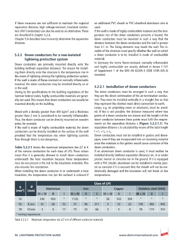
Table 5.2.2.1 shows the maximum temperature rise ΔT in K down conductors.
of the various conductors for each class of LPS. These values If an aluminium down conductor is used, it must neither be
mean that it is generally allowed to install down conductors installed directly (without separation distance) on, in or under
underneath the heat insulation because these temperature plaster, mortar or concrete nor in the ground. If it is equipped
rises do not present a fire risk to the insulation materials. This with a PVC sheath, aluminium can be installed in mortar, plas-
also ensures fire retardation. ter or concrete if it is ensured that the sheath will not be me-
When installing the down conductor in or underneath a heat chanically damaged and the insulation will not break at low
insulation, the temperature rise (on the surface) is reduced if temperatures.
Class of LPS
q Ø
2
[mm ] [mm] Aluminium Iron Copper Stainless steel (V4A)
III + IV II I III + IV II I III + IV II I III + IV II I
16 146 454 * 1120 * * 56 143 309 * * *
50 8 mm 12 28 52 37 96 211 5 12 22 190 460 940
78 10 mm 4 9 17 15 34 66 3 5 9 78 174 310
* melting / vaporisation
Table 5.2.2.1 Maximum temperature rise ΔT in K of different conductor materials
96 LIGHTNING PROTECTION GUIDE www.dehn-international.com