
Page 579 - Din prodcuts 2020
P. 579
5/135
—
Protection and safety
Specific systems protection
OVR CCTV Series
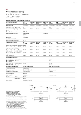
OVR CCTV Series - Technical specification
Electrical specification OVR OVR CCTV/ OVR CCTV/ OVR CCTV/ OVR OVR OVR CCTV/ OVR CCTV/
CCTV/B B-15V B-30V B-50V CCTV/T CCTV/T-15V T-30V T-50V 5
ABB order code 7TCA085400R0296 7TCA085400R0297 7TCA085400R0299 7TCA085400R0300 7TCA085400R0301 7TCA085400R0302 7TCA085400R0298 7TCA085400R0303
Nominal voltage (peak-peak) 1 V 2 V
(1)
(2)
Maximum working voltage Uc 7.79 V 16.7 V 36.7 V 56.7 V 7.79 V 16.7 V 36.7 V 56.7 V
(peak)
Current rating (signal) 300 mA
In-line resistance (±10%) 1 Ω inserted 1 Ω per line
in coax
inner
Bandwidth > 100 MHz
(-3 dB 75 Ω system) (3)
Voltage standing wave ratio < 1.2:1
Transient specification OVR OVR CCTV/ OVR CCTV/ OVR CCTV/ OVR OVR OVR CCTV/ OVR CCTV/
CCTV/B B-15V B-30V B-50V CCTV/T CCTV/T-15V T-30V T-50V
Let-through voltage (all conductors)(4) Up
C2 test 4 kV 1.2/50 μs, 2 kA 8/20 μs 39.5 V 55.0 V 78.0 V 105.0 V 39.5 V 55.0 V 78.0 V 105.0 V
to BS EN/EN/IEC 61643-21
C1 test 1 kV 1.2/50 μs, 0.5 kA 26.0 V 42.0 V 66.5 V 93.5 V 26.0 V 42.0 V 66.5 V 93.5 V
8/20 μs to BS EN/EN/IEC 61643-21
B2 test 4 kV 10/700 μs to BS EN/ 16.0 V 27.2 V 47.5 V 73.6 V 16.0 V 27.2 V 47.5 V 73.6 V
EN/IEC 61643-21
5 kV, 10/700 μs (5) 17.0 V 28.2 V 49.5 V 76.2 V 17.0 V 28.2 V 49.5 V 76.2 V
Maximum surge current (6)
D1 test 10/350 – Per signal wire 2.5 kA 2.5 kA
μs to BS EN/EN/ – Per pair – 5 kA
IEC 61643-21
8/20 μs to ITU – Per signal wire 10 kA 10 kA
(formerly CCITT) – Per pair – 20 kA
Mechanical specification OVR CCTV/B variants OVR CCTV/T variants
Temperature range -40 to +80 °C
Connection type Coaxial BNC female Screw terminal
Conductor size (stranded) Not applicable 2.5 mm 2
Earth connection M6 stud
Case Material ABS UL94 V-0 ABS UL94 V-0
Weight – Unit 0.08 kg
– Packaged 0.9 kg
Dimensions See diagram below
CCTV/B CCTV/T
54 mm 54 mm 54 mm 54 mm
38 mm 38 mm 38 mm 38 mm
(1) Nominal voltage (DC or AC peak)
measured at < 10 μA leakage 105 mm 105 mm 105 mm
105 mm
(2) Maximum working voltage (DC or M4 clearance M4 clearance M4 clearance
M4 clearance
AC peak) measured at 5 mA leakage
(3) Capacitance < 30 pF 120 mm 144 mm 120 mm 144 mm
(4) The maximum transient voltage let-through of the
protector throughout the test (±10%), line to line 19 mm
19 mm
& line to earth. Screen to earth let-through voltage
will be up to 600 V (with 5 kV 10/700 test), when 109 mm 109 mm 109 mm
109 mm
protector is configured for use with non-earthed M4 clearance M4 clearance M4 clearance
M4 clearance
or isolated screen systems. Response time < 10 ns
(5) Test to IEC 61000-4-5:2006, ITU-T (formerly
CCITT) K.20, K.21 and K.45,Telcordia
GR-1089-CORE, Issue 2:2002, ANSI TIA/EIA/
IS-968-A:2002 (formerly FCC Part 68)
(6) The installation and connectors external to the
protector may limit the capability of the protector