
Page 577 - Din prodcuts 2020
P. 577
5/133
—
Protection and safety
Specific systems protection
OVR RF Series
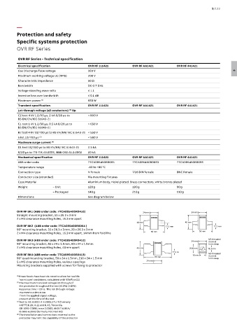
OVR RF Series - Technical specification
Electrical specification OVR RF 111421 OVR RF AA1421 OVR RF 441421
Gas Discharge Tube voltage 350 V 5
Maximum working voltage Uc (RMS) 200 V
Characteristic impedance 50 Ω
Bandwidth DC-2.7 GHz
Voltage standing wave ratio ≤ 1.1
Insertion loss over bandwidth ≤ 0.1 dB
Maximum power (1) 650 W
Transient specification OVR RF 111421 OVR RF AA1421 OVR RF 441421
Let-through voltage (all conductors) Up
(2)
C2 test 4 kV 1.2/50 μs, 2 kA 8/20 μs to < 800 V
BS EN/EN/IEC 61643-21
C1 test 1 kV 1.2/50 μs, 0.5 kA 8/20 μs to < 650 V
BS EN/EN/IEC 61643-21
B2 test 4 kV 10/700 μs to BS EN/EN/IEC 61643-21 < 550 V
5 kV, 10/700 μs (3) < 580 V
Maximum surge current (4)
D1 test 10/350 μs to BS EN/EN/IEC 61643-21 2.5 kA
8/20 μs to ITU-T K.45:2003, IEEE C62.41.2:2002 20 kA
Mechanical specification OVR RF 111421 OVR RF AA1421 OVR RF 441421
ABB order code 7TCA085450R0065 7TCA085450R0063 7TCA085450R0066
Temperature range -40 to +80 °C 24 mm
24 mm
Connection type N female 7⁄16 DIN female BNC female
Conductor size (stranded) Via mounting fixtures 40 mm
40 mm 17.3 mm
Case Material Aluminium body, nickel plated. Brass connectors, white bronze plated
17.3 mm
Weight – Unit 120 g 190 g 90 g 58 mm
24 mm 58 mm
– Packaged 140 g 210 g 110 g 24 mm
Dimensions See diagram below
40 mm
40 mm 17.3 mm
17.3 mm
78 mm
OVR RF BK1 (ABB order code: 7TCA085400R0416) 24 mm 24 mm 78 mm
Straight mounting bracket, 53 x 26.3 x 3 mm 24 mm 24 mm
2 x M4 clearance mounting holes, 16.3 mm apart
40 mm 40 mm
OVR RF BK2 (ABB order code: 7TCA085400R0064 ) 40 mm 17.3 mm 40 mm 17.3 mm
90° mounting bracket, 33 x 26.3 x 3 mm, 20 x 26.3 x 3 mm 17.3 mm 56 mm 17.3 mm
2 x M4 clearance mounting holes, 16.3 mm apart, 14 mm from fold line 58 mm
24 mm 58 mm 56 mm M3 threaded
24 mm 24 mm channel,
OVR RF BK3 (ABB order code: 7TCA085400R0412) 24 mm M3 threaded
5 mm deep
channel,
90° mounting bracket, 50 x 24 x 1.5 mm, 60 x 24 x 1.5 mm 40 mm 25.8 mm 19.3 mm
5 mm deep
2 x M5 clearance mounting holes, 40 mm apart 40 mm 25.8 mm
17.3 mm 19.3 mm
M3 threaded
17.3 mm 18 mm channel,
OVR RF BK4 (ABB order code: 7TCA085400R0413) 78 mm 18 mm M3 threaded
5 mm deep
channel,
90° quad mounting bracket, 50 x 24 x 1.5 mm, 210 x 24 x 1.5 mm 24 mm 78 mm 5 mm deep
5 x M5 clearance mounting holes, various spacings 24 mm
Mounting brackets supplied with screws for fixing to protector
40 mm
40 mm
17.3 mm
17.3 mm
(1) Power levels have been de-rated to allow for real life
56 mm
‘worst case’ conditions, calculated with VSWR as 2:1 56 mm
(2) The maximum transient voltage let-through of 24 mm M3 threaded
channel,
M3 threaded
the protector throughout the test (±10%) (±10%). 24 mm 5 mm deep
channel,
Response time < 10 ns. This let-through voltage 25.8 mm 19.3 mm
5 mm deep
represents a deviation 25.8 mm 19.3 mm
from the applied signal voltage, 18 mm M3 threaded
present at the time of the test 18 mm channel,
M3 threaded
channel,
(3) Test to IEC 61000-4-5:2006, ITU-T (formerly 5 mm deep
5 mm deep
CCITT) K.20, K.21 and K.45, Telcordia
GR-1089-CORE, Issue 2:2002, ANSI TIA/EIA/
IS-968-A:2002 (formerly FCC Part 68)
(4) The installation and connections external to the
protector may limit the capability of the protector