
Page 24 - Sace Emax 2 Manual Touch Protection breakers
P. 24
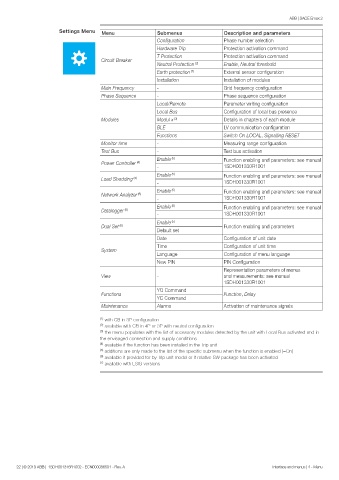
ABB | SACE Emax 2
                      Settings Menu  Menu               Submenus                Description and parameters
                                                        Configuration           Phase number selection
                                                        Hardware Trip           Protection activation command
                                                        T Protection            Protection activation command
                                     Circuit Breaker
                                                        Neutral Protection  (2)  Enable, Neutral threshold
                                                        Earth protection  (7)   External sensor configuration
                                                        Installation            Installation of modules
                                     Main Frequency     -                       Grid frequency configuration
                                     Phase Sequence     -                       Phase sequence configuration
                                                        Local/Remote            Parameter writing configuration
                                                        Local Bus               Configuration of local bus presence
                                     Modules            Modul x  (3)            Details in chapters of each module
                                                        BLE                     LV communication configuration
                                                        Functions               Switch On LOCAL, Signalling RESET
                                     Monitor time       -                       Measuring range configuration
                                     Test Bus           -                       Test bus activation
                                                        Enable  (5)             Function enabling and parameters: see manual
                                     Power Controller  (4)
                                                        -                       1SDH001330R1001
                                                        Enable  (5)             Function enabling and parameters: see manual
                                     Load Shedding  (4)
                                                        -                       1SDH001330R1001
                                                        Enable  (5)             Function enabling and parameters: see manual
                                     Network Analyzer  (6)
                                                        -                       1SDH001330R1001
                                                        Enable  (5)             Function enabling and parameters: see manual
                                     Datalogger  (6)
                                                        -                       1SDH001330R1001
                                                        Enable  (5)
                                     Dual Set  (6)                              Function enabling and parameters
                                                        Default set
                                                        Date                    Configuration of unit date
                                                        Time                    Configuration of unit time
                                     System
                                                        Language                Configuration of menu language
                                                        New PIN                 PIN Configuration
                                                                                Representation parameters of menus
                                     View               -                       and measurements: see manual
                                                                                1SDH001330R1001
                                                        YO Command
                                     Functions                                  Function, Delay
                                                        YC Command
                                     Maintenance        Alarms                  Activation of maintenance signals

                                    (1)  with CB in 3P configuration
                                    (2)  available with CB in 4P or 3P with neutral configuration
                                    (3)  the menu populates with the list of accessory modules detected by the unit with Local Bus activated and in
                                    the envisaged connection and supply conditions
                                    (4)  available if the function has been installed in the Trip unit
                                    (5)  additions are only made to the list of the specific submenu when the function is enabled (=On)
                                    (6)  available if provided for by Trip unit model or if relative SW package has been activated
                                    (7)  available with LSIG versions


       22 | © 2019 ABB |  1SDH001316R1002 - ECN000086501 - Rev. A                                Interface and menus | 4 - Menu