
Page 112 - 35_DS702_E_2014_Lightning_Protection_Guide
P. 112
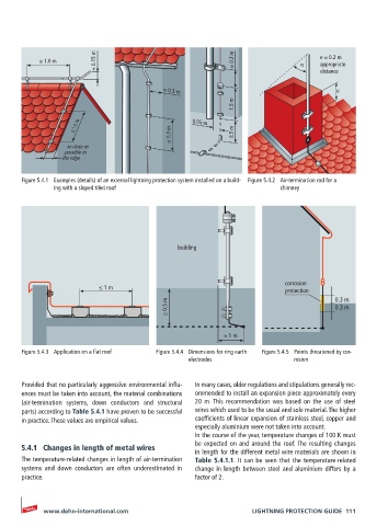
≤ 1.0 m        ≈ 0.15 m                            ≈ 0.3 m           α    e ≈ 0.2 m
                                                                                     appropriate
                                                                                     distance

                                            ≈ 0.3 m                                       e
                                                              1.5 m


                    ≤ 1.0 m                         0.05 m
                                              ≤ 1.0 m         0.5 m

                   as close as
                  possible to
                 the edge

       Figure 5.4.1  Examples (details) of an external lightning protection system installed on a build-  Figure 5.4.2  Air-termination rod for a
               ing with a sloped tiled roof                                chimney


                                                building


                                                                            corrosion
                           ≤ 1 m                                            protection
                                             ≥ 0.5 m                                     0.3 m
                                                                                         0.3 m


                                                            ≈ 1 m

       Figure 5.4.3  Application on a flat roof  Figure 5.4.4  Dimensions for ring earth   Figure 5.4.5  Points threatened by cor-
                                                   electrodes                 rosion


       Provided that no particularly aggressive environmental influ-  In many cases, older regulations and stipulations generally rec-
       ences must be taken into account, the material combinations   ommended to install an expansion piece approximately every
       (air-termination systems, down conductors and structural   20 m. This recommendation was based on the use of steel
       parts) according to Table 5.4.1 have proven to be successful   wires which used to be the usual and sole material. The higher
       in practice. These values are empirical values.  coefficients of linear expansion of stainless steel, copper and
                                                    especially aluminium were not taken into account.
                                                    In the course of the year, temperature changes of 100 K must
       5.4.1  Changes in length of metal wires      be expected on and around the roof. The resulting changes
                                                    in length for the different metal wire materials are shown in
       The temperature-related changes in length of air-termination   Table 5.4.1.1. It can be seen that the temperature-related
       systems and down conductors are often underestimated in   change in length between steel and aluminium differs by a
       practice.                                    factor of 2.


            www.dehn-international.com                             LIGHTNING PROTECTION GUIDE  111